Reaction vessel, reaction apparatus and reaction solution temperature control method

a technology of reaction apparatus and temperature control method, which is applied in the field of reaction apparatus and reaction solution temperature control method, can solve the problems of drop in the amplification efficiency of pcr, and it is difficult to utilize a pcr reaction apparatus comprising a micro-capillary as a pcr reaction vessel, so as to achieve efficient, control the temperature of the reaction solution more quickly, and achieve efficient

Inactive Publication Date: 2006-09-14
PRECISION SYST SCI
View PDF2 Cites 33 Cited by
  • Summary
  • Abstract
  • Description
  • Claims
  • Application Information

AI Technical Summary

Benefits of technology

[0043] In a desirable aspect of the temperature control method of the present invention, the reaction solution is pressed in the step (a) so that the contact area between the reaction solution and the reaction chamber is increased. In this aspect, the pressing of the reaction solution in step (a) is performed so that the contact area between the reaction solution and the reaction chamber is increased compared to that in the state prior to the pressing of the reaction solution. For example, the pressing of the reaction solution in step (a) can be performed so that the contact area between the reaction solution and the reaction chamber increases gradually or stepwise as the reaction solution is pressed. In this aspect, the movement of heat via the contact surface between the reaction solution and the reaction chamber can be accomplished efficiently by pressing the reaction solution so that the contact area between the reaction solution and the reaction chamber is increased, thus making it possible to control the temperature of the reaction solution more quickly.
[0044] In a desirable aspect of the temperature control method of the present invention, the reaction solution is pressed in the step (a) so that the contact area between the reaction solution and the pressing member is increased. In this aspect, for example, the pressing of the reaction solution in step (a) is performed so that the contact area between the reaction solution and the pressing member increases gradually or stepwise as the reaction solution is pressed. In this aspect, the movement of heat via the contact surface between the reaction solution and the pressing member can be accomplished efficiently by pressing the reaction solution so that the contact area between the reaction solution and the pressing member increases, thus making it possible to control the temperature of the reaction solution more quickly.
[0045] In a desirable aspect of the temperature control method of the present invention, the reaction solution is pressed in the step (a) so that the reaction solution assumes a thin configuration. In this aspect, the contact area between the reaction solution and the reaction chamber and the contact area between the reaction solution and the pressing member can be increased to a much greater extent by pressing the reaction solution so that the reaction solution assumes a thin configuration. As a result, the movement of heat via the contact surface between the reaction solution and the reaction chamber and the contact surface between the reaction solution and the pressing member can be accomplished efficiently, so that the temperature of the reaction solution can be controlled more quickly. Furthermore, in this aspect, temperature control of the reaction solution can be accomplished uniformly with respect to the reaction solution as a whole, so that the temperature of the reaction solution can be controlled with good precision. Moreover, in this aspect, most of the surface area of the reaction solution can be formed into a contact surface with the reaction chamber and pressing member; as a result, the contact area between the reaction solution and gases such as air or the like that are present inside the reaction chamber can be reduced to a much greater extent, so that the evaporation of the reaction solution into these gases such as air or the like that are present inside the reaction chamber can be suppressed more efficiently.
[0046] In a desirable aspect of the temperature control method of the present invention, the reaction solution is a PCR reaction solution. In this aspect, the reaction that is caused to proceed inside the reaction chamber is a PCR. In the case of a PCR, the temperature of the reaction solution must be controlled over time or periodically; since the temperature control method of the present invention makes it possible to achieve quick control of the temperature of the reaction solution, the time required for such a PCR can be shortened by using the temperature control method of the present invention.

Problems solved by technology

Furthermore, if air is admixed when the reaction solution is enclosed inside the micro-capillaries, this air will expand as a result of the heating that is performed in the process of the PCR, so that the reaction solution will move through the micro-capillaries, thus causing a drop in the amplification efficiency of the PCR.
Accordingly, it is difficult to utilize a PCR reaction apparatus comprising a micro-capillary as a PCR reaction vessel for the automation of the series of operations comprising the preparation of samples containing target nucleic acids (extraction of nucleic acids from cells), amplification of the target nucleic acids by means of a PCR, and analysis of the target nucleic acids.

Method used


Image

  • Reaction vessel, reaction apparatus and reaction solution temperature control method
  • Reaction vessel, reaction apparatus and reaction solution temperature control method
  • Reaction vessel, reaction apparatus and reaction solution temperature control method

Examples


Embodiment Construction

[0061] Below, embodiments of the reaction vessel of the present invention will be described with reference to the attached figures.

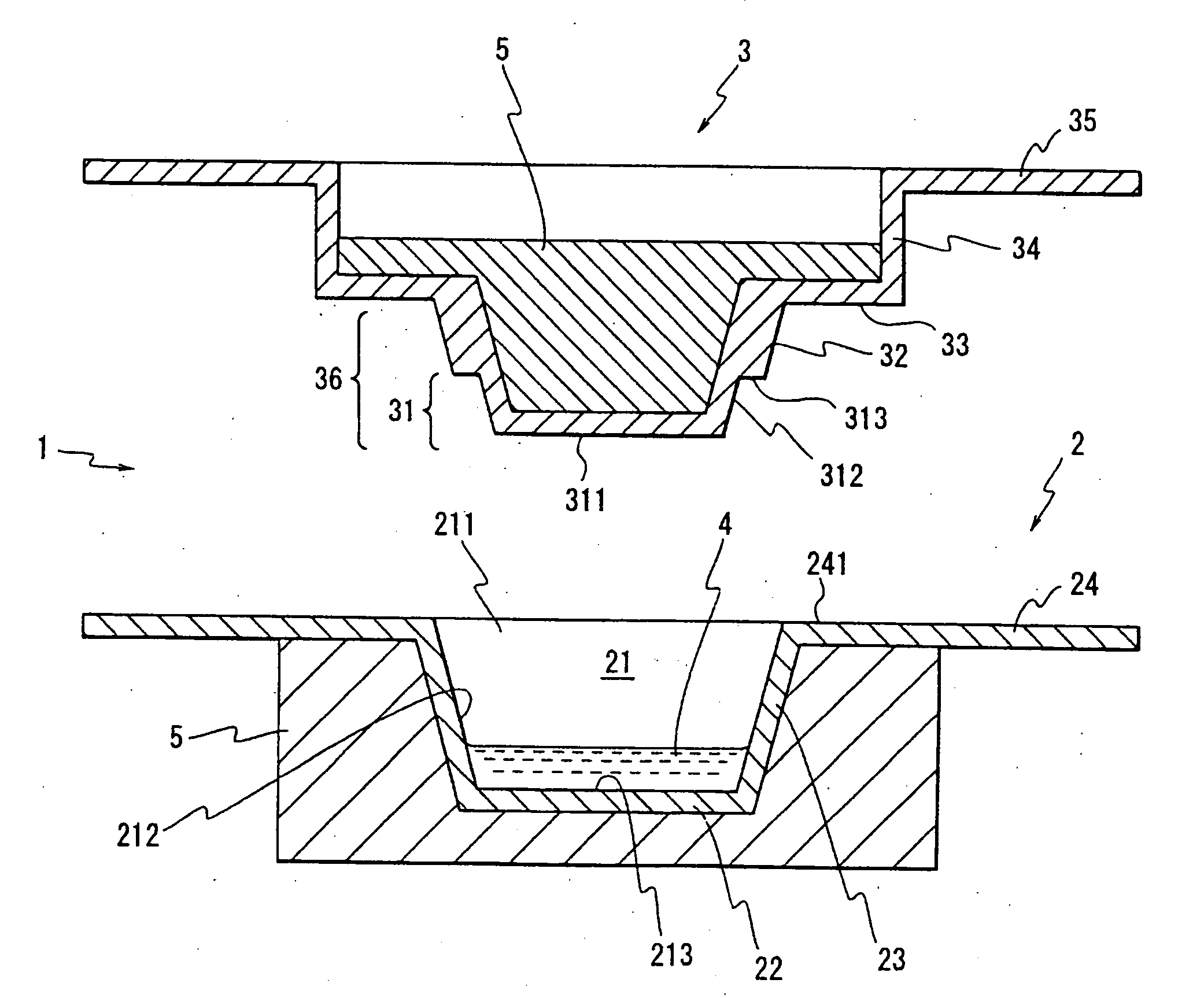
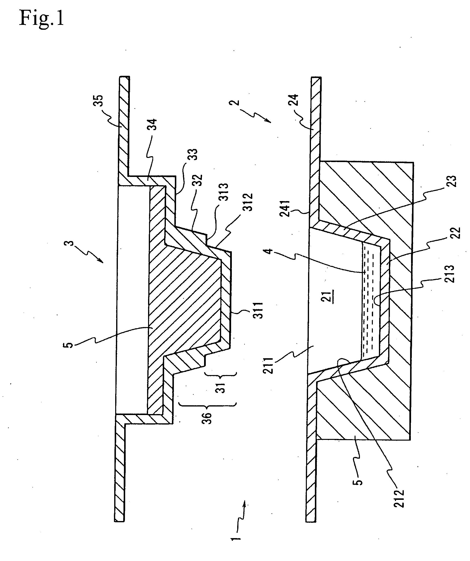
[0062]FIG. 1 is a sectional view showing one embodiment of the reaction vessel of the present invention.

[0063] As is shown in FIG. 1, the reaction vessel 1 of the present embodiment comprises a reaction vessel main body 2, a cover member 3, and a heat-conducting metal block 5.

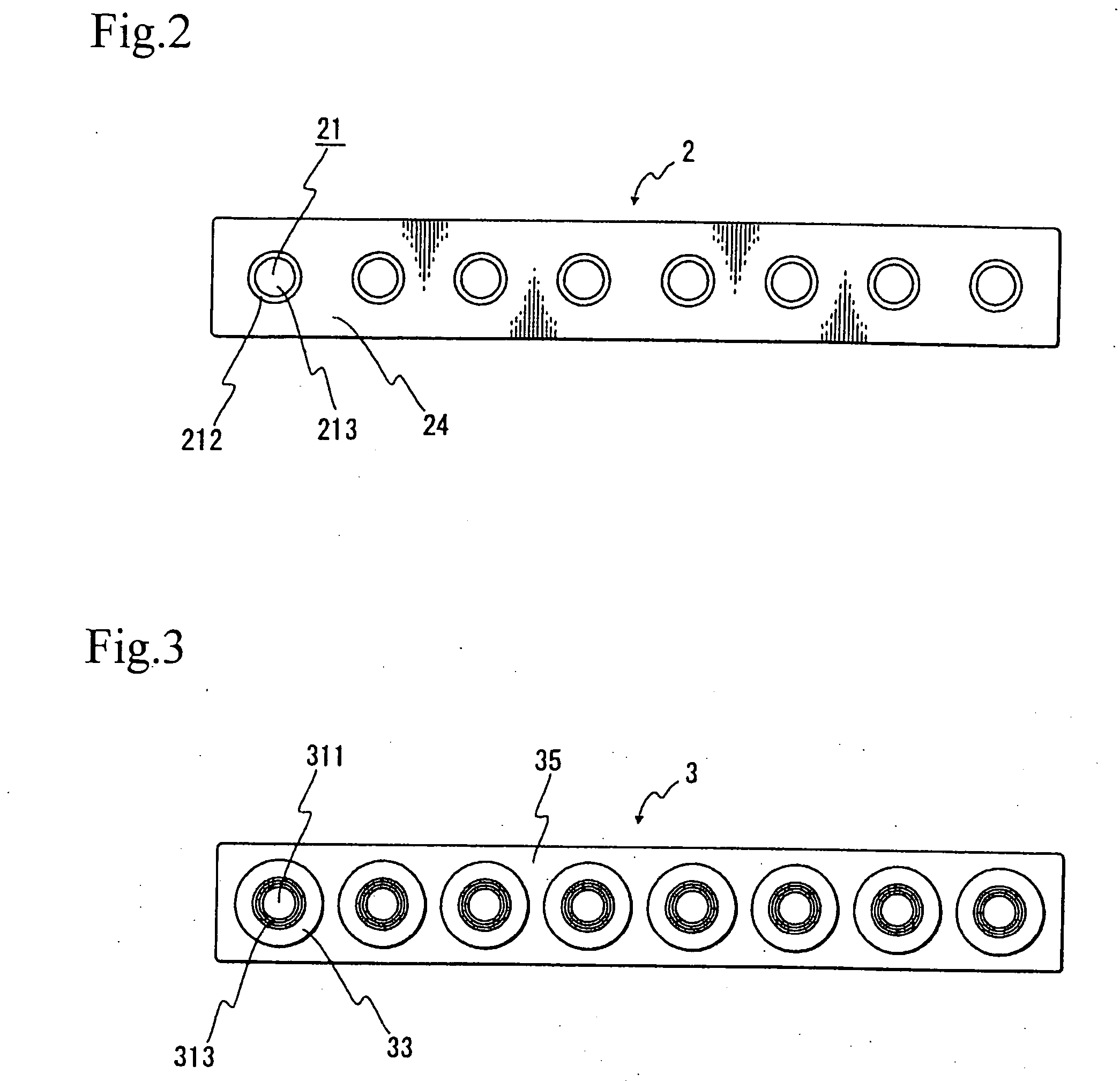
[0064]FIG. 2 is a plan view of the reaction vessel main body 2 in the present embodiment, and FIG. 3 is a bottom view of the cover member 3 in the present embodiment.

[0065] As is shown in FIGS. 1 and 2, the reaction vessel main body 2 is constructed from a circular bottom plate part 22, a tubular part 23 which is installed in an upright position so that this tubular part 23 gradually increases in diameter in the upward direction from the circumferential edge of the bottom plate part 22, and a flat-plate part 24 which is disposed on the upper end of the tubular part 23.

[0066] As...


PUM

PropertyMeasurementUnit
temperatureaaaaaaaaaa

Abstract

It is an object of the present invention to provide a reaction vessel which makes it possible to control the temperature of the reaction solution accommodated in the reaction chamber with a quick response, without any need for centrifuging when the reaction solution is accommodated in the reaction chamber, and which also makes it possible to cause the reaction to proceed even when the amount of reaction solution accommodated in the reaction chamber is extremely small. The present invention provides a reaction vessel comprising a reaction vessel main body which has a reaction chamber that has an opening part in the upper end and that can accommodate a reaction solution, and a cover member which can seal the opening part of the abovementioned reaction chamber, wherein the abovementioned cover member has a pressing part that can press the reaction solution accommodated in the abovementioned reaction chamber.

Description

TECHNICAL FIELD [0001] The present invention relates to a reaction vessel (especially a reaction vessel which can be suitable used for a reaction requiring temperature control), a reaction apparatus utilizing this reaction vessel, and a reaction solution temperature control method. BACKGROUND ART [0002] A polymerase chain reaction (hereafter referred to as “PCR”) is a technique which amplifies target nucleic acids by a rise and fall in temperature utilizing a heat-resistant polymerase and primers. This technique is widely used in fields such as genetic engineering, biological test methods and detection methods and the like. [0003] The principle of PCR lies in the fact that target DNA is amplified in a geometrical progression by numerous repetitions of a cycle according to a thermal profile (rise and fall of temperature) that is set in three stages, i.e., a first stage in which the temperature is maintained at a temperature that dissociates double-stranded DNA containing a target DNA...

Claims


Application Information

Patent Timeline
Patent Type & Authority Applications(United States)
IPC IPC(8): C12M1/22C12N15/09B01J19/00B01L3/00B01L7/00C12M1/00C12M1/38C12Q1/68
CPCB01J19/0013B01J19/004B01J19/0093B01J2219/00162B01J2219/00783B01J2219/00788B01J2219/00869B01J2219/00873B01L3/50851B01L3/50853B01L7/52B01L2300/042B01L2300/0829B01L2300/1805C12Q1/686
Inventor TAJIMA, HIDEJI
Owner PRECISION SYST SCI
Why Eureka
Try Eureka