
System for monitoring a drying process

a technology for drying process and monitoring system, applied in the field of sensors, can solve the problems of non-intrusive sensors and many commercial freeze-drying processes, and achieve the effects of saving time, improving efficiency, and accurately measuring

Inactive Publication Date: 2006-09-21
PHYSICAL SCI
View PDF13 Cites 52 Cited by
  • Summary
  • Abstract
  • Description
  • Claims
  • Application Information

AI Technical Summary

Benefits of technology

[0018] Implementations can realize one or more of the following advantages. A sensor of the technology can be used to continuously monitor a process, to determine the freeze-drying process primary drying endpoint, the freeze-drying process secondary drying endpoint, and the process can be stopped when an experimentally determined endpoint has been reached. For example, for a freeze-drying process, when a desired level of moisture removal has been achieved, the freeze drying process can be stopped, which can save time and improve efficiency. The determination of the primary drying endpoint can be used to control the temperature of the drying chamber shelf temperature and advance the drying process to secondary drying. The technology provides a non-contact optical sensor using optical access via a duct that can be placed in-line in a freeze-drying apparatus. The technology features the capability of being remotely operated via fiber optic transmission of the laser light and wireless transmission of data signals, which can limit worker exposure to active pharmaceutical ingredients, thereby ensuring worker safety and product quality. The technology also provides a measurement technology capable of accurately measuring solvent or water vapor temperature and measuring gas flow velocities throughout the primary and secondary drying phases of a freeze-drying process. The technology provides a system to facilitate scaling a laboratory scale freeze-dryer to a large, commercial scale freeze dryers. One implementation of the invention provides at least one of the above advantages.

Problems solved by technology

Despite decades of usage and its widespread utility, many commercial freeze-drying processes are not optimal because of the complexity, and the lack of, adequate process analytical technology.
Few non-intrusive sensors exist for monitoring critical process parameters, such as product temperature, solvent sublimation and evaporation rates, vapor mass flux, and timing of the change in shelf temperature from primary drying conditions to secondary drying conditions.
Many freeze-drying processes are empirically developed in the laboratory through trial and error, and are suboptimal when they are scaled up from the laboratory to a commercial freeze-drying process because they do not address dryer mass and or heat transfer overload.

Method used


Image

  • System for monitoring a drying process
  • System for monitoring a drying process
  • System for monitoring a drying process

Examples


Embodiment Construction

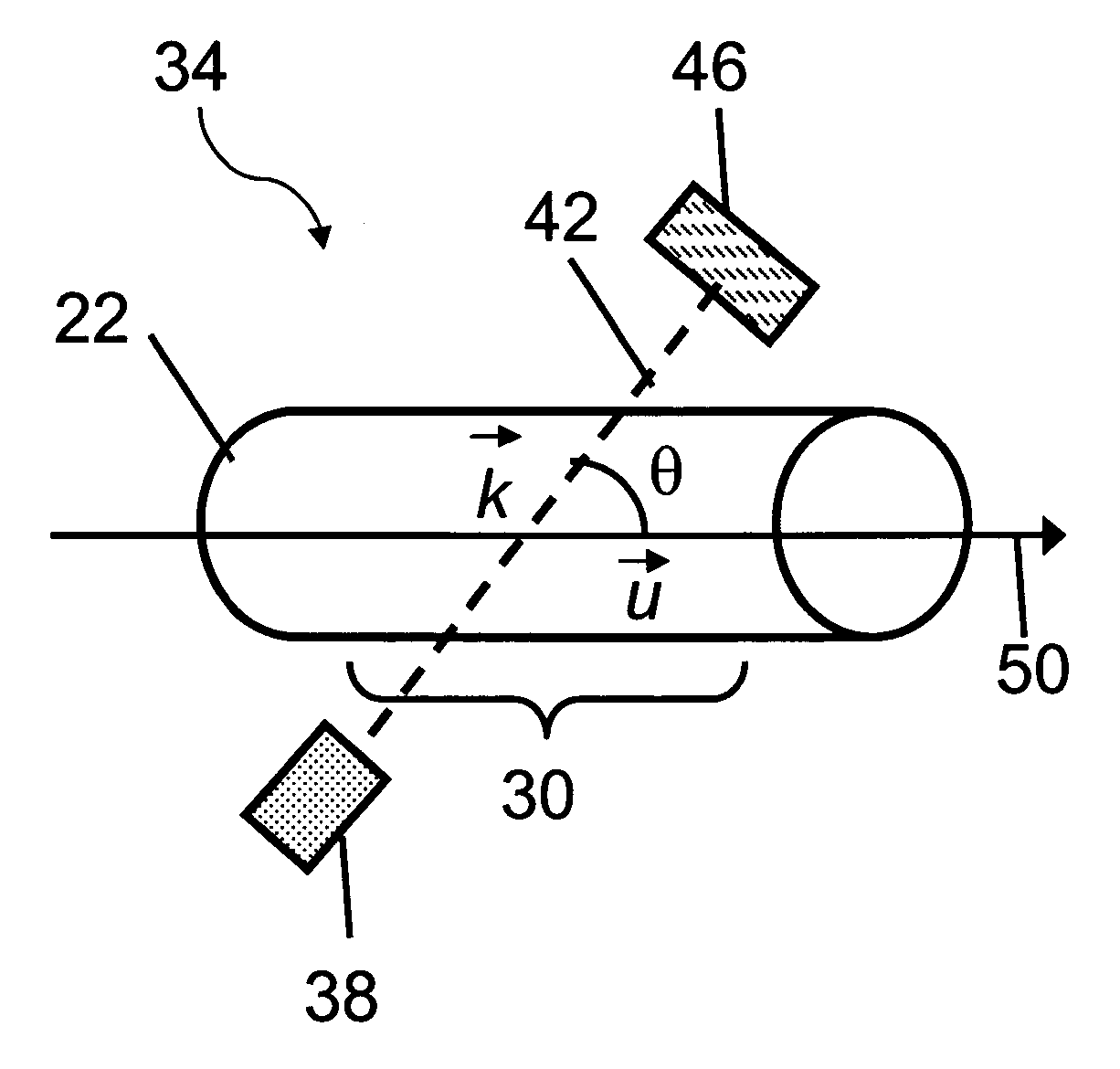
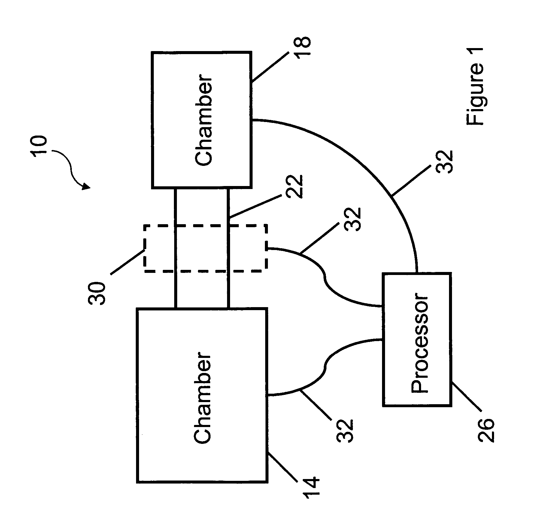
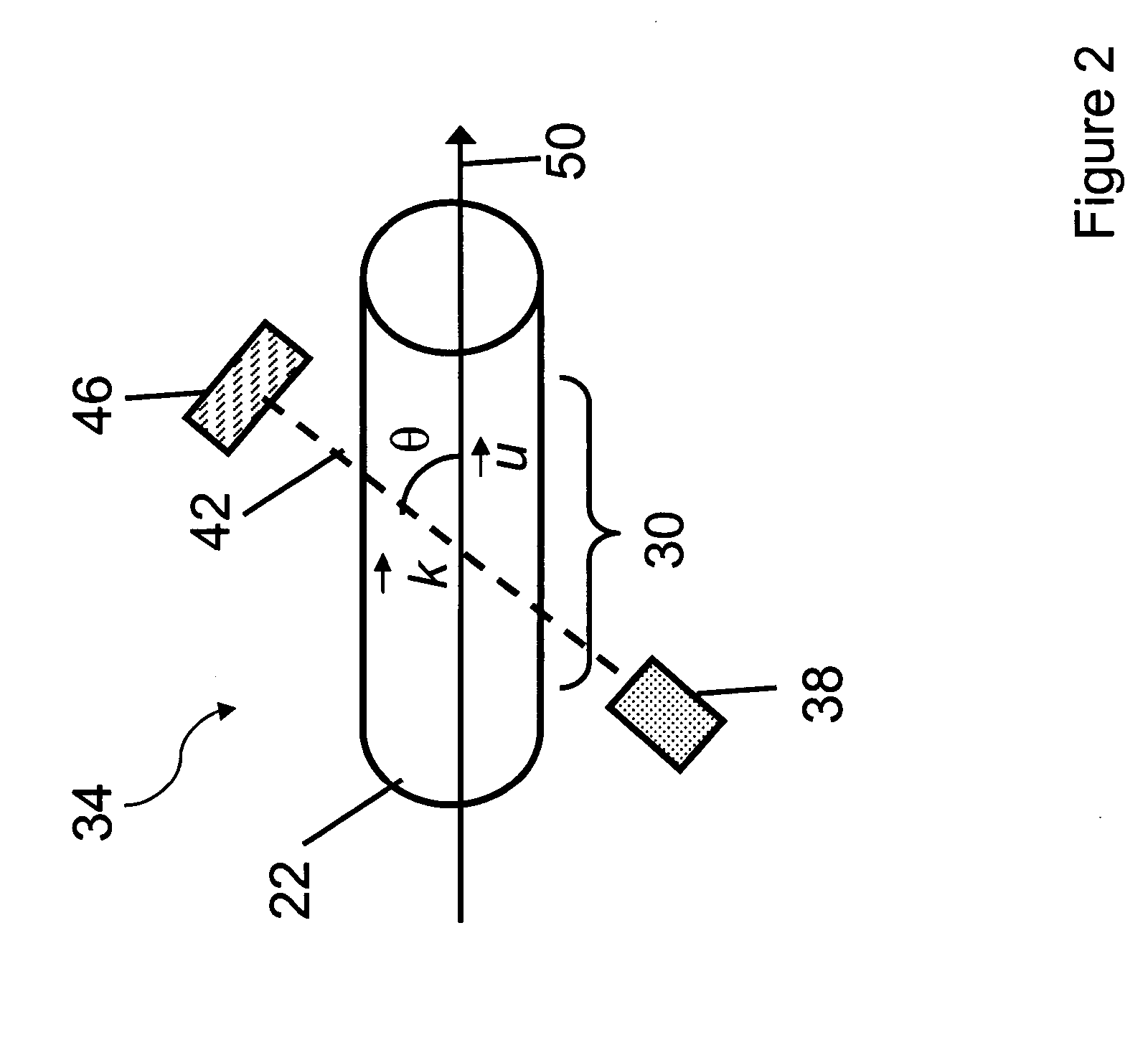
[0033]FIG. 1 shows an illustrative embodiment of an apparatus 10 for applying the optical detection system during a drying process of a product. The apparatus 10 includes a first chamber 14, a second chamber 18, a duct 22, and a processor 26. The duct 22 includes a diagnostic region 30. The duct 22 defines a bore, through which a gas can flow when exiting the first chamber 14. The diagnostic region 30 can include an optical detection system (e.g., as shown in FIGS. 2, 4, 6, or 7) for measuring at least one parameter associated with the gas flowing through the bore of the duct 22. The apparatus 10 can be at high pressure or low-pressure.

[0034] The processor 26 can receive data from the diagnostic region 30. In some embodiments, the processor 26 can provide feedback to the first chamber 14 or the second chamber 18 to control processing of the product. Data transmission to and from the processor 26 can occur using a cable or cables 32, or via a wireless transmission.

[0035] In various...


PUM

PropertyMeasurementUnit
pressuresaaaaaaaaaa
wavelength tuningaaaaaaaaaa
angleaaaaaaaaaa

Abstract

An apparatus for monitoring a parameter of a solvent during a drying process is described. The apparatus includes a light source providing at least one light beam and a detection system receiving a signal corresponding to the at least one light beam transmitted through a vapor of the solvent flowing through a diagnostic region. A processor can determine from the signal at least one solvent parameter associated with the vapor of the solvent, and the processor can determine from the at least one solvent parameter the instantaneous mass flux of the vapor of the solvent.

Description

CROSS-REFERENCE TO RELATED APPLICATION [0001] This application claims the benefit of and priority to U.S. provisional patent application No. 60 / 642,297 filed Jan. 7, 2005, which is owned by the assignee of the instant application and the disclosure of which is incorporated herein by reference in its entirety.GOVERNMENT RIGHTS [0002] The government may have certain rights in portions of the invention made with government support under Contract No. DMI-0339202 awarded by the National Science Foundation.FIELD OF THE INVENTION [0003] The invention relates generally to a method and apparatus for monitoring a solvent during a drying process, and more particularly, to a sensing system that can be used to determine the vapor mass flux of a solvent. BACKGROUND OF THE INVENTION [0004] Freeze-drying or lyophilization is a process in which water or an alternative solvent is removed from a liquid product to produce a dry, stable cake that can be reconstituted for use at a later time. Freeze-dryi...

Claims


Application Information

Patent Timeline
Patent Type & Authority Applications(United States)
IPC IPC(8): G01N1/10G01J5/02
CPCF26B5/06G01J5/58G01N21/31
Inventor KESSLER, WILLIAM J.DAVIS, STEVEN J.MULHALL, PHILLIP A.FINSON, MICHAEL L.
Owner PHYSICAL SCI
Learn More