Motor frive inverter control apparatus

a technology of inverter control and motor frive, which is applied in the direction of motor/generator/converter stopper, dynamo-electric converter control, dynamo-electric gear control, etc. it can solve the problems of power supply voltage rapidly rising, over-voltage sometimes degrades respective driving elements, and cannot fully absorb regenerative energy. to achieve the effect of preventing deformation

Inactive Publication Date: 2006-09-21
PANASONIC CORP
View PDF2 Cites 43 Cited by
  • Summary
  • Abstract
  • Description
  • Claims
  • Application Information

AI Technical Summary

Benefits of technology

[0017] The foregoing structure allows the first and the second capacitors to absorb regenerative energy produced by the motor at its slowdown or halt, so that respective driving elements are prevented from degrading, and also a downsized and inexpensive apparatus is obtainable.

Problems solved by technology

At that time, since smoothing capacitor 3 has a small enough capacity, it cannot fully absorb the regenerative energy.
As a result, the power supply voltage rapidly rises, and an over-voltage sometimes degrades respective driving elements.

Method used


Image

  • Motor frive inverter control apparatus
  • Motor frive inverter control apparatus
  • Motor frive inverter control apparatus

Examples


embodiment 1

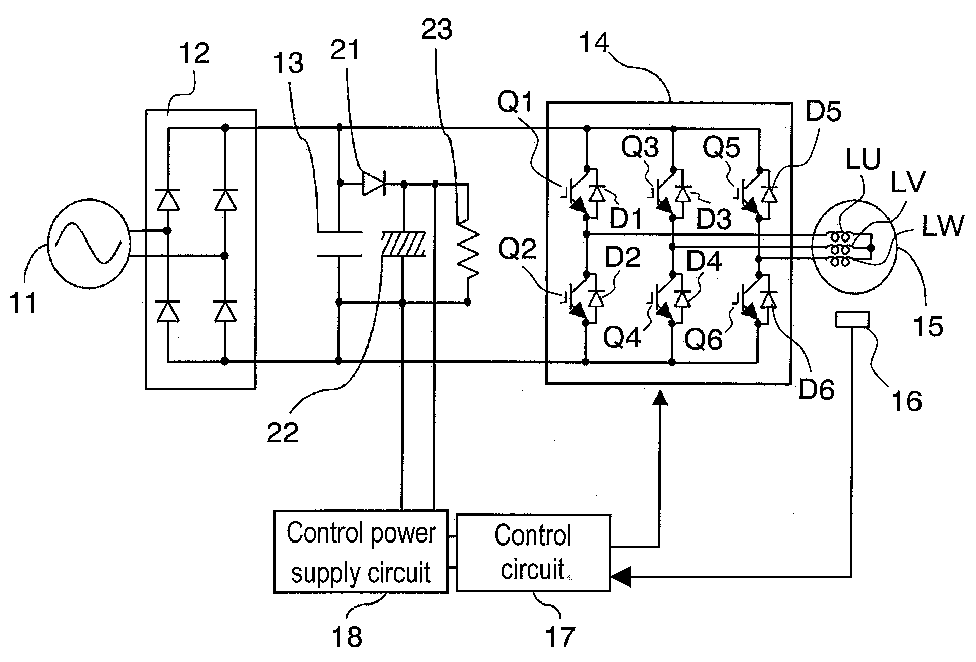
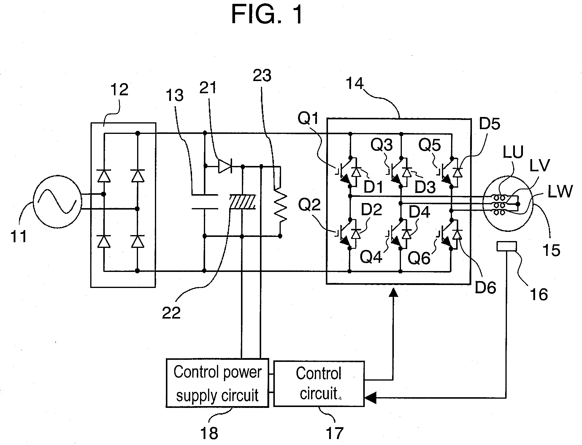
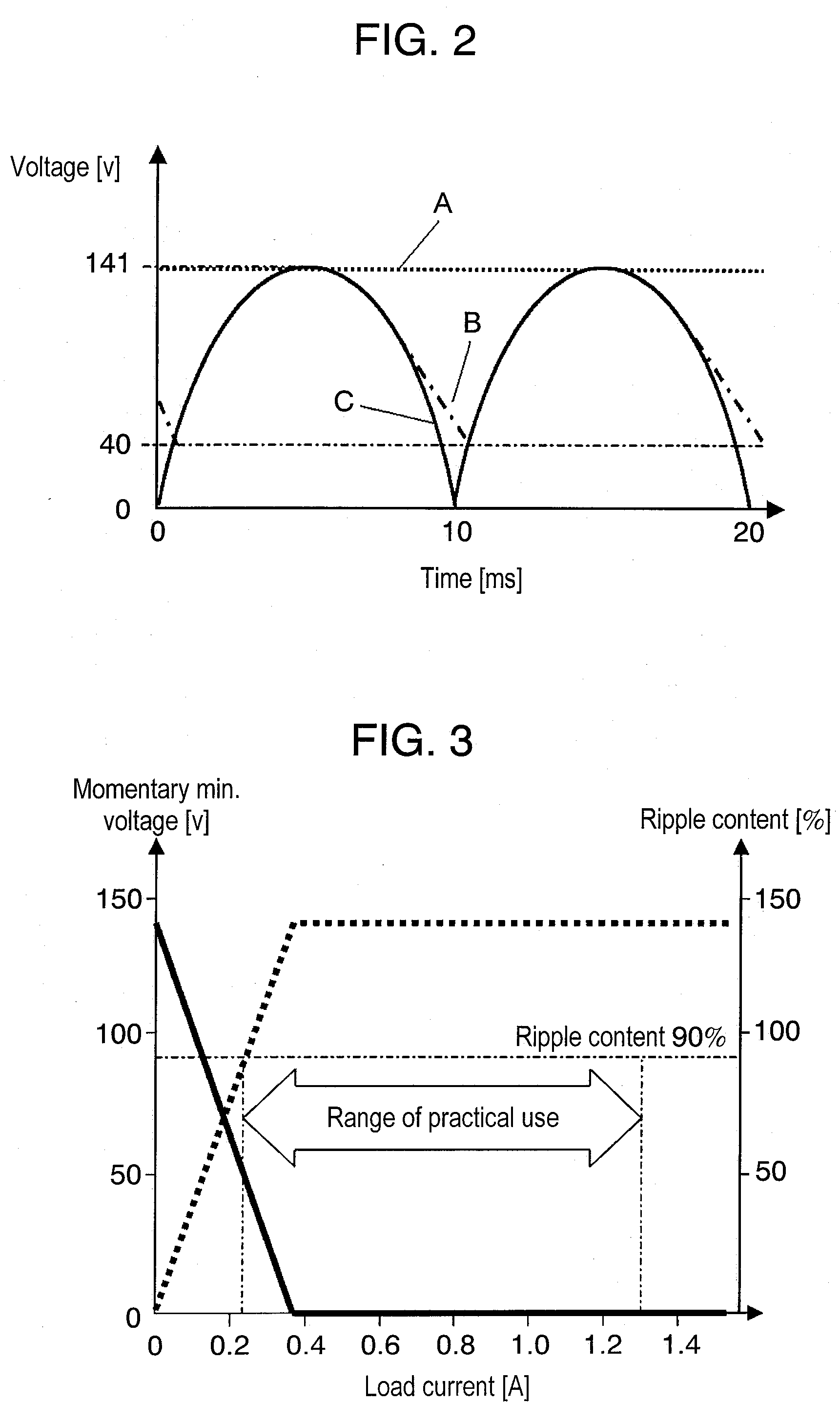
[0035]FIG. 1 shows a block diagram illustrating a motor drive inverter control apparatus in accordance with the first embodiment of the present invention. FIG. 2 shows a timing chart illustrating a voltage waveform of first capacitor 13 used in the first embodiment. FIG. 3 shows characteristics of a load current, a ripple content, and a momentary minimum voltage. FIG. 4 shows characteristics of respective voltages across first capacitor 13 and second capacitor 22 in accordance with the first embodiment.

[0036] The motor drive inverter control apparatus shown in FIG. 1 has the following structure:

[0037] AC power supply 11 is rectified by rectifier circuit 12, and smoothed by first capacitor 13, then the resultant DC power supply is fed into inverter circuit 14. Inverter circuit 14 is formed of switching elements Q1, Q2, Q3, Q4, Q5 and Q6 coupled to each other into a three-phase bridge and flywheel diodes D1, D2, D3, D4, D5 and D6. Those flywheel diodes are coupled in inversely paral...

embodiment 2

[0067]FIG. 5 shows a block diagram illustrating a motor drive inverter control apparatus in accordance with the second embodiment of the present invention. The same structural elements as those used in the first embodiment have the same reference marks and the detailed descriptions thereof are omitted here. In this second embodiment, resistor 23 used in the first embodiment is replaced with variable load 32 (hereinafter referred to as a variable resistor), and voltage sensor 31 is provided for sensing a voltage of second capacitor 22.

[0068] An operation of the foregoing motor drive inverter control apparatus in accordance with the second embodiment is demonstrated hereinafter. First, when regenerative energy is not available, namely, when voltage sensor 31 senses a voltage across second capacitor 22 be lower than the peak value of AC power supply 11, variable resistor 32 is set at a value where the min. energy is consumed (in other words, variable resistor 32 is set at a greater va...


PUM


Abstract

A motor drive inverter control apparatus includes a rectifier circuit for rectifying an AC power supply, an inverter circuit driven by an output from the rectifier circuit, a motor driven by an output from the inverter circuit, a first capacitor coupled in parallel to the output of the rectifier circuit, and a second capacitor coupled in parallel to the first capacitor via a diode. The second capacitor has capacitance not less than three times that of the first capacitor. Although the second capacitor shows a ripple content not less than 90% during practical use, it well absorbs regenerative energy produced by the motor. As a result, elements of the apparatus can be prevented from degrading caused by an over-voltage, and the apparatus can be downsized and reduced its cost.

Description

FIELD OF THE INVENTION [0001] The present invention relates to motor drive inverter control apparatuses to be mounted in compressors or blowers used in refrigerating or air-conditioning systems such as refrigerators or air conditioners. BACKGROUND OF THE INVENTION [0002] An inverter control apparatus for driving a motor mounted in a compressor or a blower used in a refrigerating or an air-conditioning system generally has the following structure: AC power fed into a refrigerating system undergoes full-wave rectification in a rectifier circuit, and passes across a smoothing capacitor having a great enough capacitance and being hooked up between output terminals. This structure allows driving an inverter with a DC power supply having a small ripple content, and also absorbing regenerative energy which is produced when the motor stops or slows down, so that an over-voltage can be prevented. [0003] In recent years, smoothing capacitors have been targeted to substantially reduce their ca...

Claims


Application Information

Patent Timeline
Patent Type & Authority Applications(United States)
IPC IPC(8): H02P27/04H02P7/00H02P21/36H02P23/06H02P27/06H02P29/02
CPCH02P23/06H02P27/06H02M7/48
Inventor TAKEOKA, YOSHINORIHAMAOKA, KOJI
Owner PANASONIC CORP
Why Eureka
Try Eureka