Three-dimensional image communication terminal and projection-type three-dimensional image display apparatus

a three-dimensional image and display apparatus technology, applied in the direction of electrical apparatus, instruments, computing, etc., can solve the problems of increasing the size of the apparatus, deteriorating the appearance of solidity, and affecting so as to enhance the appearance resolution of the image, enhance image quality, and simple configuration

Active Publication Date: 2006-09-21
PANASONIC INTELLECTUAL PROPERTY CORP OF AMERICA
View PDF5 Cites 31 Cited by
  • Summary
  • Abstract
  • Description
  • Claims
  • Application Information

AI Technical Summary

Benefits of technology

[0011] The present invention is contrived to solve the above-mentioned problems. An object of the present invention is to provide a three-dimensional image display apparatus which can reproduce a three-dimensional image having an appearance of solidity with a simple configuration.
[0012] According to an aspect of the present invention for accomplishing the above-mentioned object, there is provided a three-dimensional image display apparatus comprising: a display unit for displaying two-dimensional element images having a plurality of viewing-point images containing information on a parallax and an image at th...

Problems solved by technology

Accordingly, since the optical image path is spatially and periodically formed at the right-eye position and the left-eye position, the appearance of solidity is deteriorated when the optical image paths depart from the fixed positions.
In addition, since images having a horizontal parallax are formed in principle, the appearance of solidity is deteriorated when the right-eye position and the left-eye position depart from the horizontal direction.
However, in this case, there is a problem that the apparatus increases in size and thus markers should be attached to the observer so as to sense the positions of the eyes or the position of the face.
However, when a human being views a three-dimensional image and the profile of the lens is clear, decrease in resolution occurs due to recognition of t...

Method used


Image

  • Three-dimensional image communication terminal and projection-type three-dimensional image display apparatus
  • Three-dimensional image communication terminal and projection-type three-dimensional image display apparatus
  • Three-dimensional image communication terminal and projection-type three-dimensional image display apparatus

Examples


first embodiment

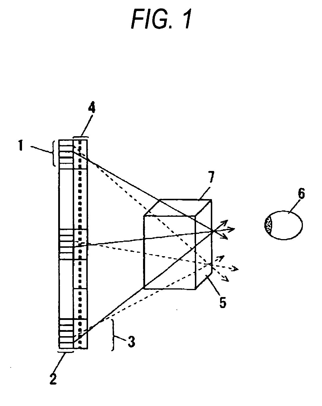
[0062] A three-dimensional image display apparatus according to a first embodiment of the present invention will be now described with reference to FIGS. 1 to 3. FIG. 1 is a diagram illustrating a configuration of the three-dimensional image display apparatus according to the first embodiment of the invention. In FIG. 1, a reference numeral 1 denotes a horizontal and vertical parallax image displayed by the three-dimensional image display apparatus, a reference numeral 2 denotes a display device for displaying the horizontal and vertical parallax image 1, a reference numeral 3 denotes a lens for forming parallax images of the horizontal and vertical parallax image 1 in a space, and a reference numeral 3 denotes a lens array in which the lenses 3 are collected in a plane shape.

[0063] The three-dimensional image display apparatus including the horizontal and vertical parallax images 1, the display device 2, and the lens array 4 having a plurality of lenses 3 displays a three-dimensio...

second embodiment

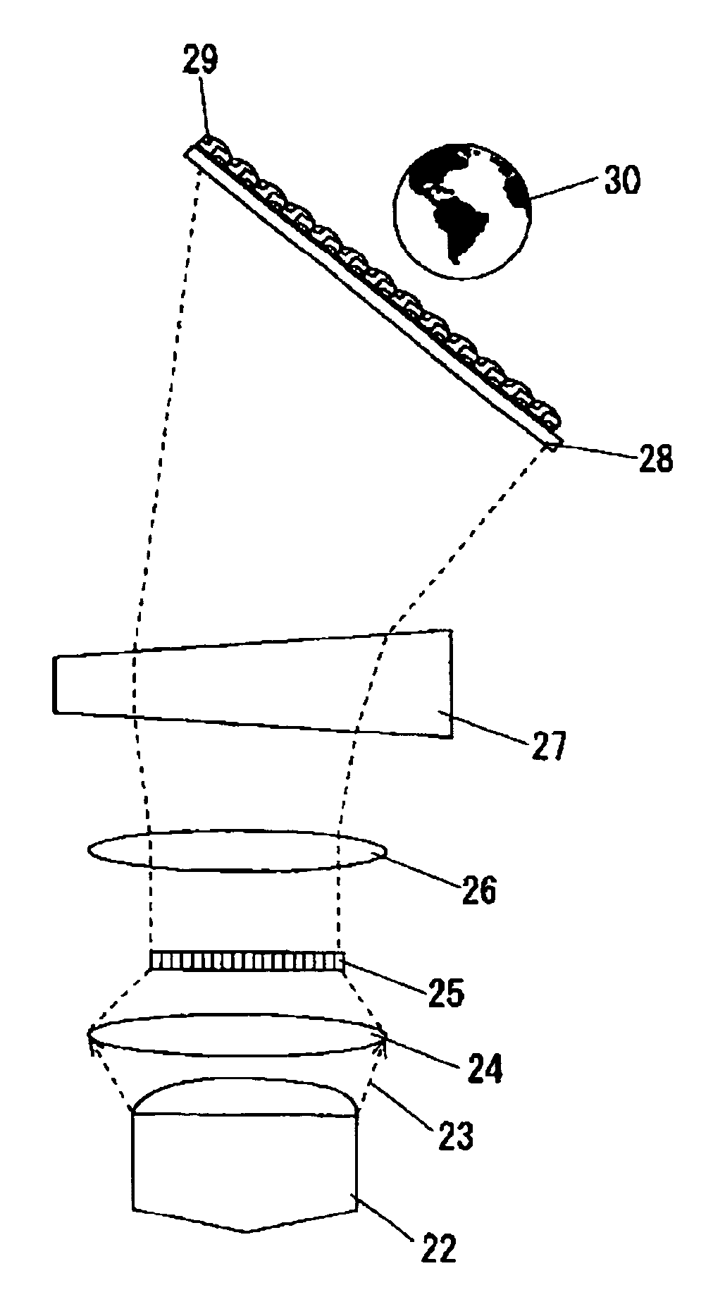
[0077] Next, a projection-type three-dimensional image display apparatus according to a second embodiment of the present invention will be described with reference to FIGS. 4 and 5. FIG. 4 is a diagram illustrating a configuration of the three-dimensional image display apparatus according to the second embodiment of the present invention. In FIG. 4, a reference numeral 22 denotes a light source, a reference numeral 23 denotes light emitted from the light source 22, a reference numeral 24 denotes a condenser lens, a reference numeral 25 denotes a projection device, a reference numeral 26 denotes a projection lens, a reference numeral 27 denotes a prism, a reference numeral 28 denotes an image forming screen, a reference numeral 29 denotes a binary optical element employing a diffraction effect, and a reference numeral 30 denotes a three-dimensional solid image.

[0078] The light source 22 is a device for emitting the light 23 and includes, for example, a white light emitting diode (LE...

third embodiment

[0095] A three-dimensional image display apparatus according to a third embodiment of the present invention will be now described with reference to FIGS. 6 and 7. FIG. 6 is a diagram illustrating a configuration of the three-dimensional image display apparatus according to the third embodiment of the present invention. In FIG. 6, a reference numeral 1 denotes a horizontal and vertical parallax image displayed by the three-dimensional image display apparatus, a reference numeral 2 denotes a display device for displaying the horizontal and vertical parallax image 1, a reference numeral 6 denotes a lens for forming parallax images of the horizontal and vertical parallax image 1 in a space, and a reference numeral 44 denotes a lens array in which the lenses 6 are collected in a plane shape.

[0096] The three-dimensional image display apparatus including the horizontal and vertical parallax images 1, the display device 2, and the lens array 44 having a plurality of lenses 6 displays a thr...


PUM


Abstract

It is possible to provide a three-dimensional image display apparatus which can reproduce a three-dimensional image having an appearance of solidity with a simple configuration. The three-dimensional image reproduction apparatus includes: a display device 2 for displaying two-dimensional element images having a plurality of horizontal and vertical parallax images 1 containing information on a parallax and an image at the time of reproducing a three-dimensional solid image 7; and a lens 3 for forming the three-dimensional solid image 7 at a predetermined spatial intersection from the element images displayed by the display device 2. Here, the lens 3 diffracts the element images and forms the three-dimensional image by the use of a diffraction effect when the element images are emitted from the display device 2.

Description

FIELD OF THE INVENTION [0001] The present invention relates to a three-dimensional image display apparatus capable of three-dimensionally displaying an image, and more particularly, to a projection-type three-dimensional image display apparatus capable of three-dimensionally displaying an image with an excellent realistic feeling, which is widely used in the fields of image technology, amusement, entertainment, Internet, information, multimedia, communication, advertisement and promotion, medicine, art, education, design support, simulation, virtual reality, and the like. BACKGROUND INFORMATION [0002] Conventionally, as means for displaying a three-dimensional image based on information on the three-dimensional image and allowing an observer to recognize the three-dimensional image, there were known a naked-eye stereoscopic paralleling method in which a right image of two images having a binocular parallax is viewed with a right eye and a left image is viewed with a left eye, a ster...

Claims


Application Information

Patent Timeline
IPC IPC(8): G06T17/00H04N13/307
CPCH04N13/0406H04N13/0402H04N13/302H04N13/307
Inventor KUBARA, TAKASHIONO, NATSUSHI
Owner PANASONIC INTELLECTUAL PROPERTY CORP OF AMERICA
Why Eureka
Try Eureka