Exposure apparatus and device manufacturing method

Inactive Publication Date: 2006-09-21
NIKON CORP
View PDF20 Cites 97 Cited by
  • Summary
  • Abstract
  • Description
  • Claims
  • Application Information

AI Technical Summary

Benefits of technology

[0020] Through the present invention, by providing a seal member, it is possible to prevent the flow of gas between the exterior and the interior space of the holding member that holds the plurality of optical members that comprise the projection optical system. Therefore, even if the configuration is such that the interior space of the holding member is filled with a prescribed gas, it is possible to prevent the penet

Problems solved by technology

When the depth of focus δ becomes too narrow, it becomes difficult to match the substrate surface to the image plane of the projection optical system, and there is concern that the focus margin during the exposure operation will be inadequate.
In any case, in a status in which the space between the substrate surface and the end face of the optical member that is most on the substrate side of the projection optical system is filled with liquid, vibration produced by the movement of the substrate stage that supports the substrate is transmitted to the optical member at the terminating end thereof via the liquid, and there is a possibility that the pattern image projected onto the substrate via the projection optical system and the liquid will deteriorate.
Furthermore, in the aforementioned prior

Method used


Image

  • Exposure apparatus and device manufacturing method
  • Exposure apparatus and device manufacturing method
  • Exposure apparatus and device manufacturing method

Examples


first embodiment

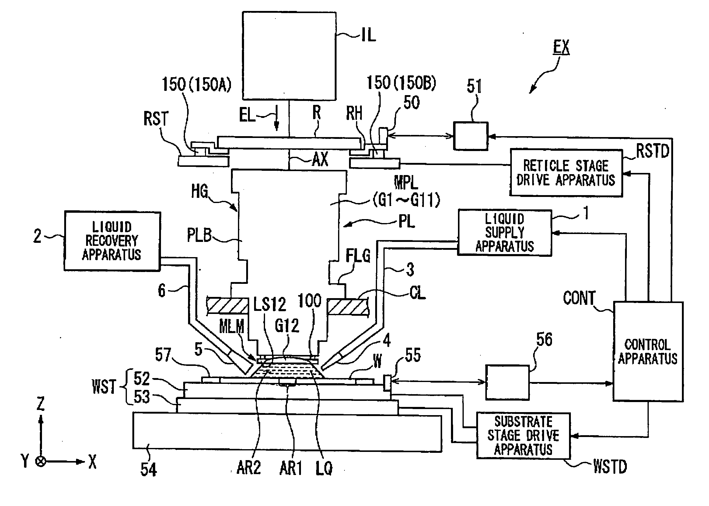
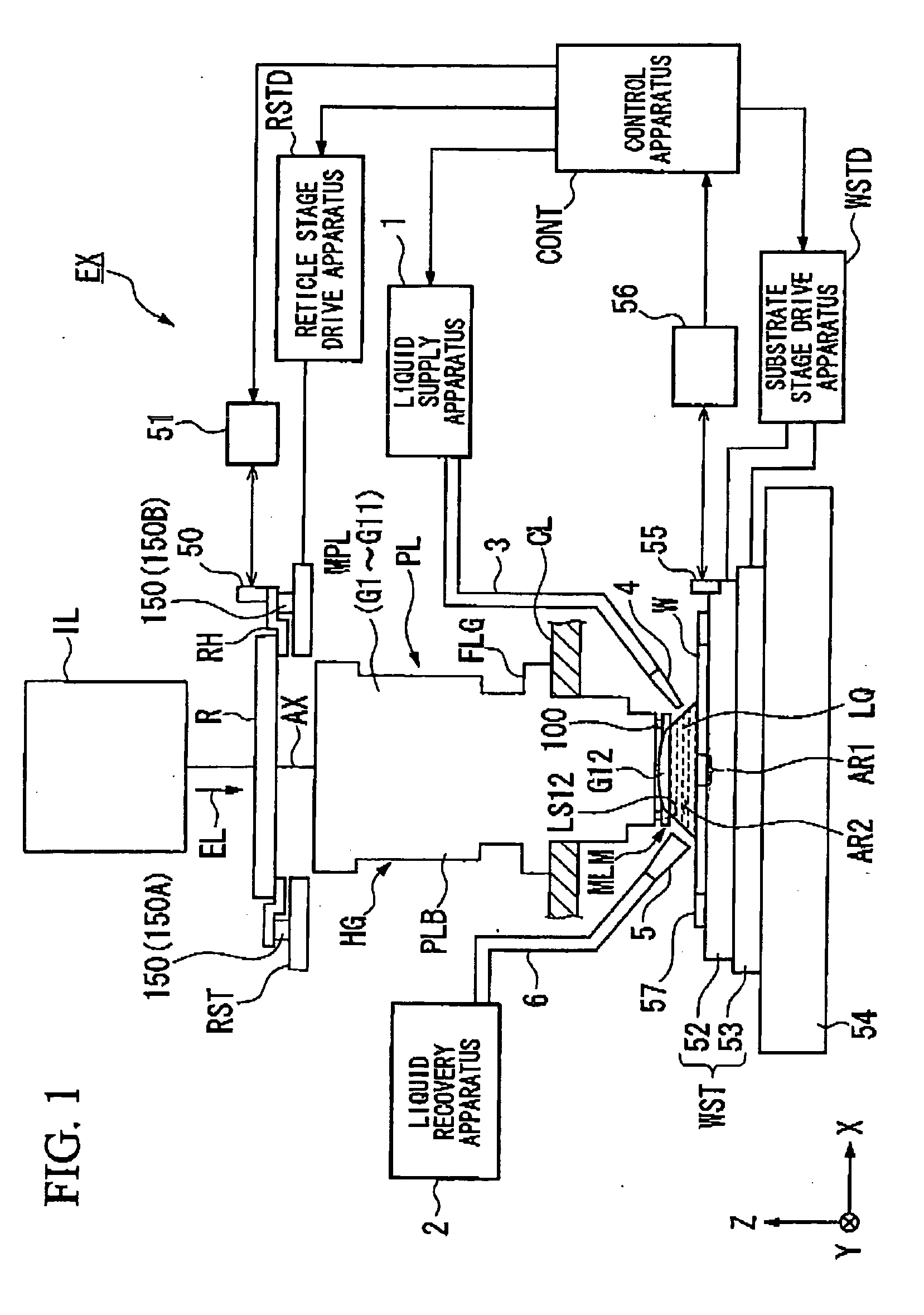
[0039]FIG. 1 is a schematic block diagram that shows an embodiment of the exposure apparatus of the present invention.

[0040] In FIG. 1, the exposure apparatus EX comprises a reticle stage RST that supports a reticle, a substrate stage WST that supports a substrate W, an illumination optical system IL that uses exposure light EL to illuminate the reticle R that is supported by the reticle stage RST, a projection optical system PL that projection exposes the pattern image of the reticle illuminated by the exposure light EL onto the substrate W supported on the substrate stage WST, and a control apparatus CONT that comprehensively controls operation of the entire exposure apparatus EX.

[0041] Here in the present embodiment, an explanation will be given which uses as an example the case of a scanning exposure apparatus (a so-called scanning stepper) that, as the exposure apparatus EX synchronously moves the reticle R and the substrate W in a direction (reverse direction) that is mutual...

second embodiment

[0090] The exposure apparatus EX of the present invention will be further explained while referring to drawings. FIG. 10 is a schematic block diagram that shows an embodiment of the exposure apparatus of the present invention.

[0091] In FIG. 10, the exposure apparatus EX comprises a mask stage MST that supports a mask 1, a substrate stage PST that supports a substrate W, an illumination optical system IL that uses exposure light EL to illuminate the mask M that is supported by the mask stage MST, a projection optical system PL that projection exposes the pattern image of the mask M illuminated by the exposure light EL onto the substrate W supported on the substrate stage PST, and a control apparatus CONT that comprehensively controls operation of the entire exposure apparatus EX.

[0092] The exposure apparatus of the present embodiment EX is a liquid immersion exposure apparatus that applies the liquid immersion method to effectively shorten the exposure wavelength to improve resolut...


PUM


Abstract

An exposure apparatus projects a pattern image onto a substrate via a projection optical system and a liquid, and the projection optical system has an optical member that comes into contact with the liquid and an optical group arranged between the optical member and a reticle. A holding mechanism that holds the optical member and the optical group holds the optical member so that it is movable relative to the optical group.

Description

CROSS-REFERENCE TO RELATED APPLICATION [0001] This is a Continuation Application of International Application No. PCT / JP2004 / 009995, filed Jul. 7, 2004, which claims priority to Japanese Patent Application Nos. 2003-272614 (filed on Jul. 9, 2003) and 2004-044801 (filed on Feb. 20, 2004). The contents of the aforementioned application are incorporated herein by reference.BACKGROUND OF THE INVENTION [0002] 1. Field of the Invention [0003] The present invention relates to an exposure apparatus that exposes a substrate in a status in which the space between the projection optical system and the substrate has been filled with a liquid, and to a device manufacturing method that uses this exposure apparatus. [0004] 2. Description of Related Art [0005] A semiconductor device or a liquid crystal display device is manufactured by the technique known as photolithography, in which a pattern formed on a mask or reticle (hereunder called ‘reticle’) is transferred onto a substrate such as a wafer ...

Claims


Application Information

Patent Timeline
IPC IPC(8): G03B27/42G02B7/02G03F7/20
CPCG02B7/021G02B7/023G03F7/70341G03F7/70825G03F7/709G03F7/2041
Inventor KIUCHI, TOHRUMIYAKE, TOSHIHIRO
Owner NIKON CORP
Why Eureka
Try Eureka