Power supply

a power supply and power supply technology, applied in emergency power supply arrangements, process and machine control, instruments, etc., can solve the problems of increased resistance, increased losses, and impracticality of transformers

Inactive Publication Date: 2006-09-21
CREATIVE TECH CORP
View PDF4 Cites 17 Cited by
  • Summary
  • Abstract
  • Description
  • Claims
  • Application Information

AI Technical Summary

Problems solved by technology

To obtain such a large inductance in the primary winding, more turns are required, which will make the transformer impractically large.
Alternatively, to avoid a large transformer, the wire used for the turns can be made thinner, but this means higher resistance which, in turn, means more losses.
Essentially, to have a very low power consumption in this arrangement, we need a perfect inductor of high inductance and this is just not feasible.
Whilst SMPS provides advantages over the first arrangement, the rapid swit...

Method used


Image

  • Power supply
  • Power supply
  • Power supply

Examples


first embodiment

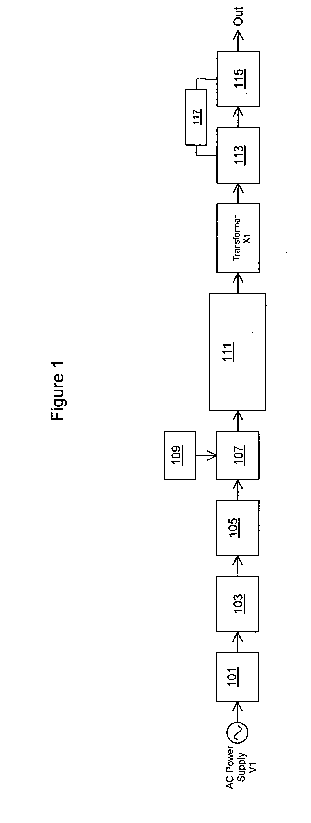
[0107]FIG. 1 is a block diagram of the invention and FIG. 2 shows a circuit implementation of that embodiment.

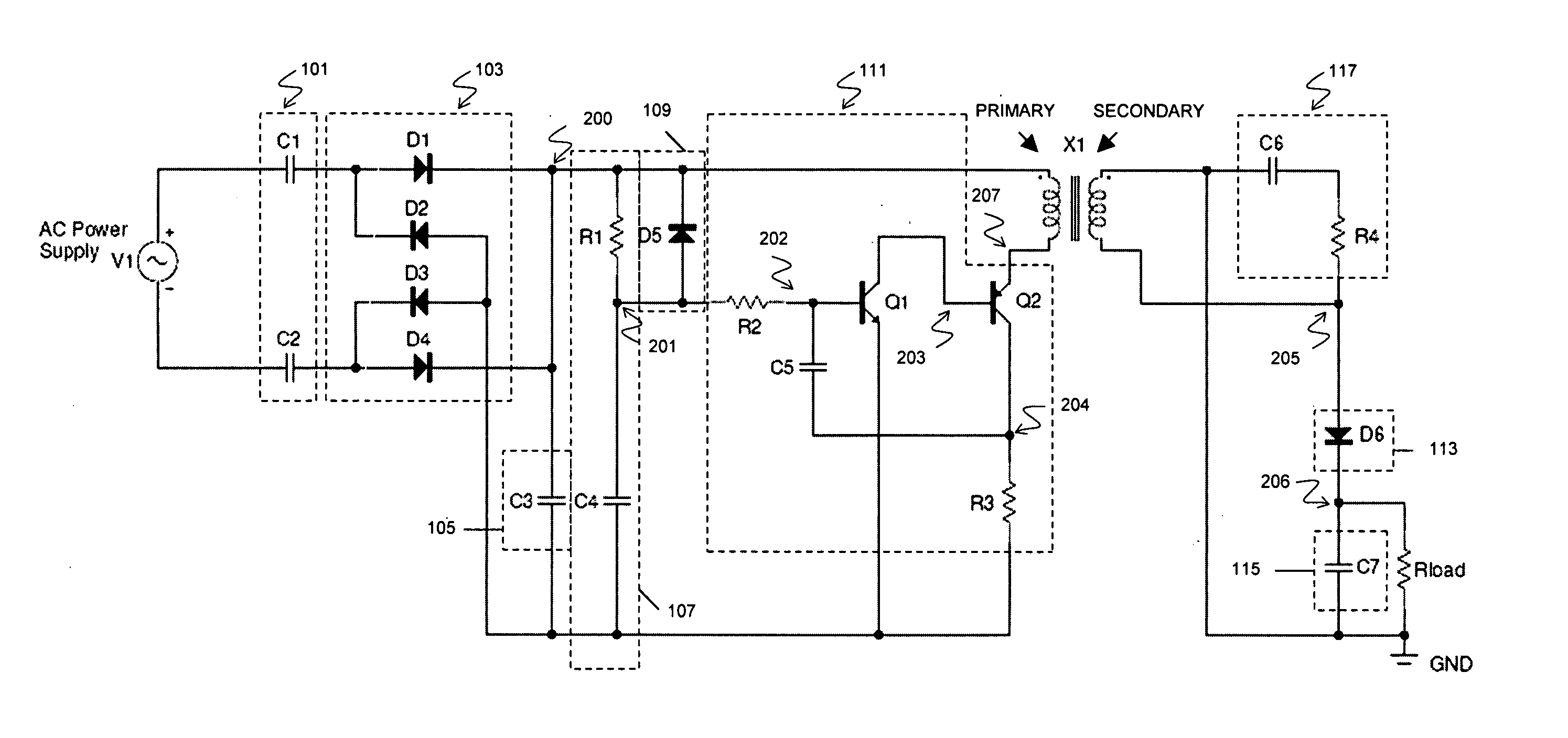
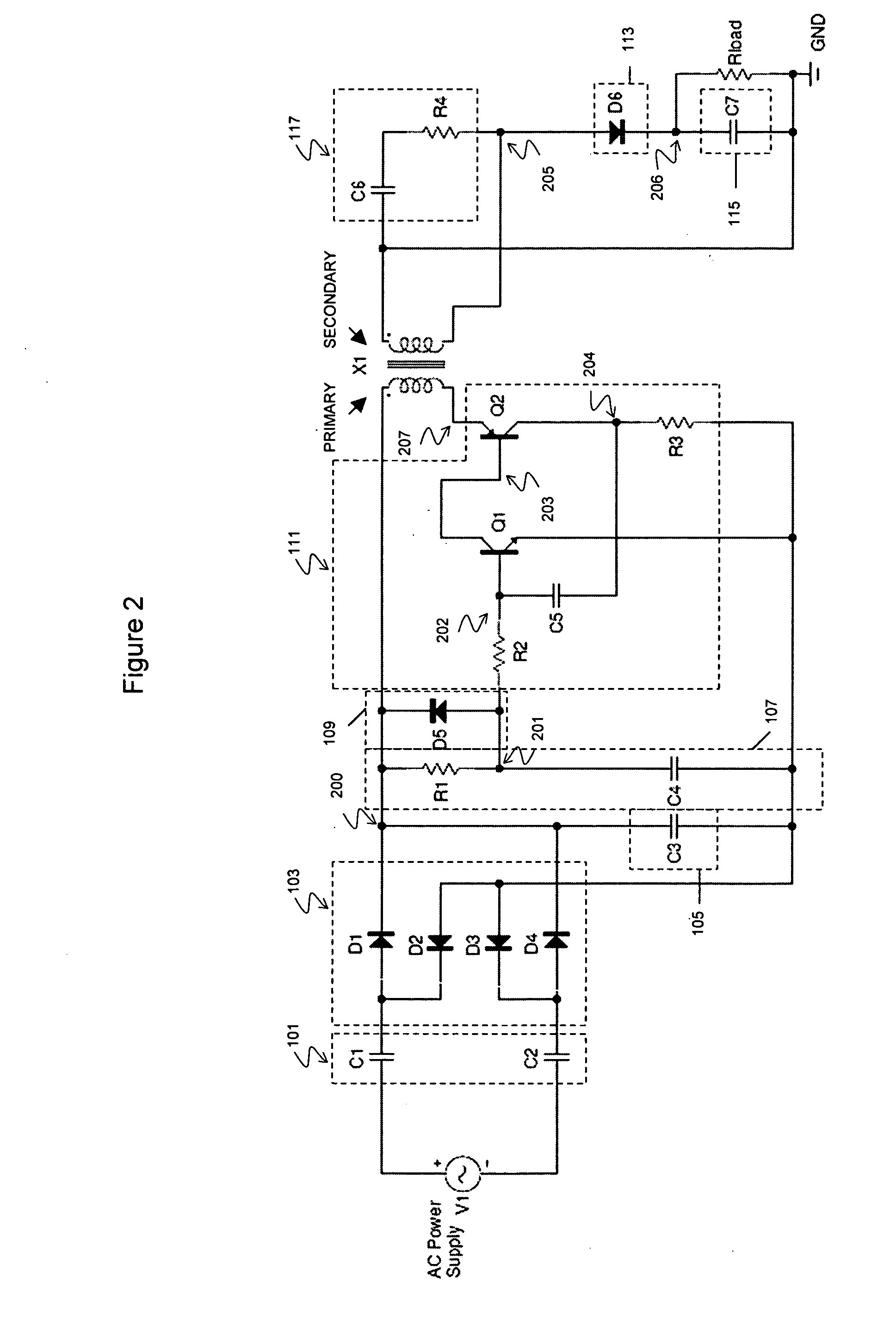
[0108] Referring to FIGS. 1 and 2, the input is AC power supply V1. The AC power supply may be any AC voltage at any frequency e.g. 110 VAC, 120 VAC, 230 VAC or 240 VAC at 50 or 60 Hz. The AC power supply V1 is connected to a current limiter 101 comprising two capacitors C1 and C2. As will be described, the power consumption may be controlled by changing the value of those capacitors. The AC signal is then rectified by rectifier 103 formed by four diodes D1, D2, D3 and D4. Note that the rectifier is a full-wave rectifier providing a DC output voltage with two maxima per AC cycle. Capacitor C3 acts as voltage limiter 105 to limit the voltage at node 200 in order to prevent the breakdown of the device due to exceedingly high voltages. If the circuit elements have a high breakdown voltage i.e. above the maximum of the AC supply peak voltage, then capacitor C3 may be omitted. Ca...

second embodiment

[0129]FIG. 8 is a block diagram of the invention and FIG. 9 shows a first circuit implementation of that embodiment.

[0130] It can be seen that the second embodiment illustrated in FIG. 8 is the same as the first embodiment except for the addition of regulator 119. That is, in summary, the arrangement includes AC power supply V1 , current limiter 101 (effected by two capacitors C1 and C2), rectifier 103 (effected by four diodes D1, D2, D3 and D4), voltage limiter 105 (capacitor C3), RC timer 107 (effected by resistor R1 and capacitor C4) and timer reset 109 (diode D5) for switch 111 (effected by transistors Q1 and Q2, resistors R2 and R3 and capacitor C5), transformer X1, rectifier 113 (diode D6), filter 115 (capacitor C7) and optional snubber circuit 117 (effected by capacitor C6 and resistor R3).

[0131] The arrangement additionally includes regulator 119. The function of regulator 119 is to reduce the fluctuation of the DC voltage at the output (node 206) to the load. This is impor...


PUM


Abstract

There is provided a power supply for an electrical device, an electrical device including such a power supply and a method for supplying power to an electrical device. The power supply comprises a transformer having primary and secondary windings. The primary winding is connectable to a AC voltage supply and circuitry on the secondary side is arranged to provide a DC output voltage for the electrical device. The power supply also comprises a switch between the primary winding of the transformer and the AC supply, a rectifier for rectifying the AC voltage, and a current limiter. The switch is arranged to switch on at some point as the rectified AC voltage increases, once it has reached a non-zero value, thereby providing a current flow through the primary winding and hence through the secondary winding. The current limiter is arranged to limit the amount of current flowing through the primary winding. The switch is arranged to switch off before the rectified AC voltage starts to increase again.

Description

FIELD OF THE INVENTION [0001] The invention relates to a power supply for an electrical device and a method for supplying power to an electrical device. In particular, the invention relates to a power supply which has low power consumption. BACKGROUND OF THE INVENTION [0002] It is becoming increasingly important to conserve energy and reduce power losses and power supplies with low power consumption are becoming more and more important. Such power supplies find applications in many situations, for example as standby power supplies in electrical devices (e.g. in televisions, washing machines), within external power supplies for supplying power to detect whether the electrical device is connected or not and to switch on the main power supply (e.g. within a portable telephone charger where the telephone is placed in a cradle for charging) or as standalone power supplies for electrical devices that require low power consumption, including low power external power supplies (e.g. a night ...

Claims


Application Information

Patent Timeline
IPC IPC(8): H02M3/335
CPCH02M3/3385H02M7/2176H02M2001/0032Y02B70/16H02M1/0032H02M7/05Y02B70/10H02J9/005
Inventor MAKINO, JUN
Owner CREATIVE TECH CORP
Why Eureka
Try Eureka