Method for detecting vibrations in a biological organism using real-time vibration imaging

a biological organism and vibration imaging technology, applied in the field of detection of vibrations, can solve the problems of harmful to the subject, methods and systems that are not suitable for applications, and generally limited to the measurement of small amplitude vibrations

Inactive Publication Date: 2006-09-21
SRI INTERNATIONAL
View PDF7 Cites 136 Cited by
  • Summary
  • Abstract
  • Description
  • Claims
  • Application Information

AI Technical Summary

Problems solved by technology

Thus, these methods and systems can be unsuitable for applications in which contact with the organism is undesirable, such as with burn victims and in defense applications.
However, LDVs have several drawbacks.
Second, they use lasers, which can potentially be harmful to the subject.
Third, they are generally limited to measurement of small amplitude vibrations, rather than the relatively large amplitude, low frequency, vibrations that are of biological interest.

Method used


Image

  • Method for detecting vibrations in a biological organism using real-time vibration imaging
  • Method for detecting vibrations in a biological organism using real-time vibration imaging
  • Method for detecting vibrations in a biological organism using real-time vibration imaging

Examples


Embodiment Construction

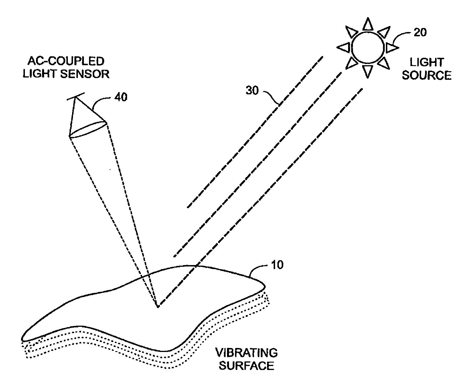
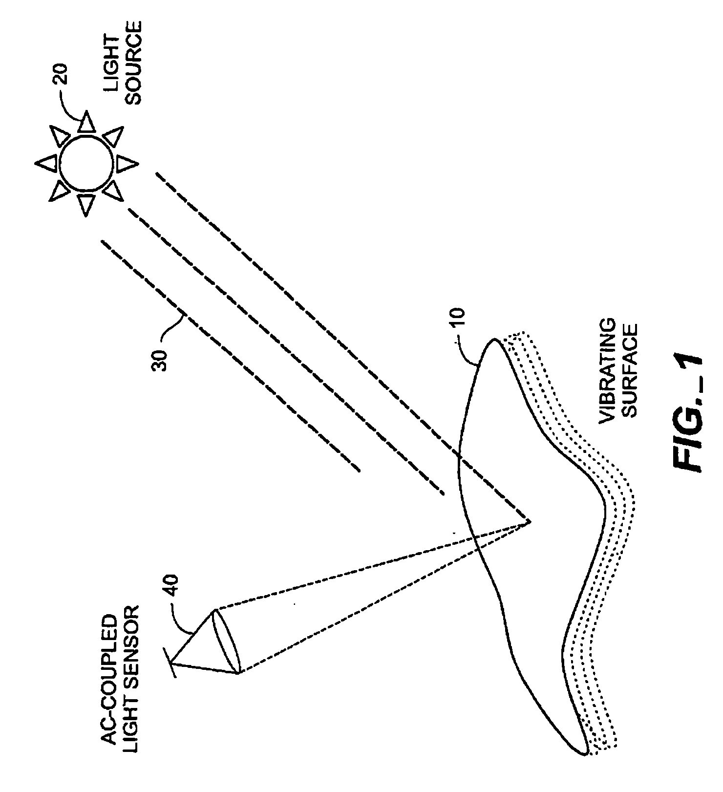
[0027] A simple example of a vibrating surface 10 is shown in FIG. 1, wherein light source 20 emits electromagnetic radiation 30, which reflects from the surface 10 and at least in part is detected at a light sensor 40. The light source 20 may in general refer to any suitable source of electromagnetic radiation, and the radiation 30 may be of any of a number of ranges of wavelengths, e.g. visible light, infrared (IR), ultraviolet, etc. Thus, when the term “light” or “optical” is used herein, it will be understood that any desired frequency or range of frequencies of electromagnetic radiation may be used, and the light source may be naturally occurring (e.g. the sun) or artificial (e.g. a laser or a lamp). The sensor 40 is accordingly configured to detect the wavelengths of interest, and as discussed below includes circuitry and software as needed to capture, process, analyze and display frequencies, relative magnitudes and phase information of the detected light substantially simult...


PUM


Abstract

The present invention provides a method for detecting vibration information by receiving electromagnetic radiation reflected or emitted from a biological organism at a light amplitude modulation detector array to provide real-time imaging of the target object. The detected radiation may be visible light, infrared or ultraviolet radiation, and / or of other desired frequency ranges. The detected radiation is preferably AC-coupled to isolate components relating to oscillations of the biological organism from components relating to ambient radiation, e.g. background sunlight. The isolated oscillations may then be digitized, stored, and subjected to processing such as a Fourier transform to generate outputs representative of frequencies of oscillation. This output can then be used for analysis of the target object.

Description

CROSS-REFERENCE TO RELATED APPLICATIONS [0001] This application is a continuation-in-part of U.S. application Ser. No. 10 / 817,116, filed Apr. 2, 2004, which claims priority from U.S. Provisional Patent Application Ser. No. 60 / 460,542 filed Apr. 3, 2003, both of which are incorporated herein by reference. FIELD OF THE INVENTION [0002] The present invention relates generally to detection of vibrations. More particularly, the present invention relates to methods of remotely detecting vibrations in a biological organism using real-time vibration imaging. BACKGROUND [0003] Various systems and methods have been used to detect biological signatures such as pulse rate, heart rate, tremor, etc. in biological organisms. Generally, these systems and methods require contact with the organism in order to function. Thus, these methods and systems can be unsuitable for applications in which contact with the organism is undesirable, such as with burn victims and in defense applications. [0004] Lase...

Claims


Application Information

Patent Timeline
Patent Type & Authority Applications(United States)
IPC IPC(8): G03B42/06G01H9/00H04B1/59
CPCA61B5/11A61B5/7257G01H9/002
Inventor MELESE, PHILIPLAVELLE, ERICDUBOIS, LAWRENCE H.DONALDSON, KATHERINE
Owner SRI INTERNATIONAL
Why Eureka
Try Eureka