Coherent light source and control method thereof, and display unit and laser display using them

Inactive Publication Date: 2006-09-21
PANASONIC CORP
View PDF9 Cites 21 Cited by
  • Summary
  • Abstract
  • Description
  • Claims
  • Application Information

AI Technical Summary

Benefits of technology

[0011] According to this aspect, the photo detector measures the higher harmonic output of a laser beam emitted from the semiconductor laser and having undergone wavelength conversion in the light wavelength conversion element. Under this condition, firstly, the current control means controls the current injection means to adjust currents applied to the active region and the distributed Bragg reflection region, so that the oscillation wavelength of the semiconductor laser is fixed to the inclined portion within the phase matching wavelength spectrum. Subsequently, the pulse current inject

Problems solved by technology

At the present time, however, because there is no semiconductor laser for green and blue capable of achieving a high output and ensuring the reliability, SHG light sources have to be used.
In this met

Method used


Image

  • Coherent light source and control method thereof, and display unit and laser display using them
  • Coherent light source and control method thereof, and display unit and laser display using them
  • Coherent light source and control method thereof, and display unit and laser display using them

Examples


first embodiment

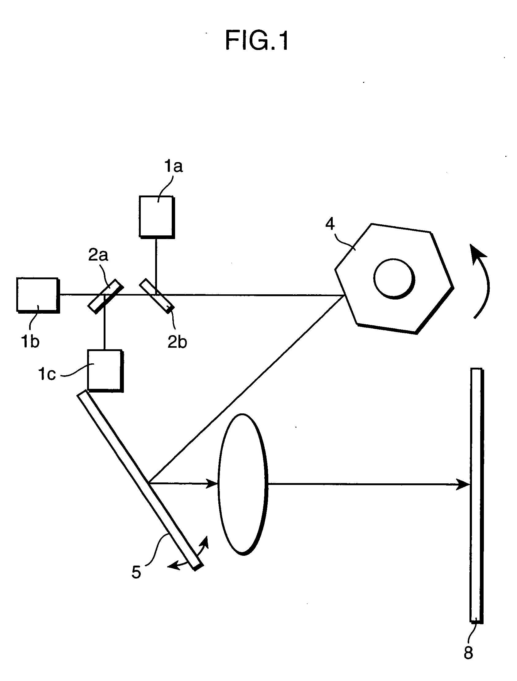
[0026]FIG. 1 schematically shows the configuration of a laser display. Referring to the drawing, beams of coherent light from laser light sources 1a through 1c of three colors, RGB, undergo intensity modulation according to an input video signal, and are then multiplexed on dichroic mirrors (multiplexing means) 2a and 2b. Further, the light is scanned in the horizontal direction by a polygon scanner (polygon mirror, first scanning means) 4 comprising a rotary polygon mirror and in the vertical direction by a galvanometer mirror (second scanning means) 5, and a two-dimensional image is displayed on a screen 8. The scanning means in the horizontal direction and the scanning means in the vertical direction are not limited to this configuration, and the polygon scanner 4 and the galvanometer mirror 5 can be combined arbitrarily. SHG light sources are used as the green light source 1b and the blue light source 1c. A semiconductor laser is used as the red light source 1a, and an output ca...

second embodiment

[0053] A second embodiment will describe a control method of an SHG light source including a semiconductor laser (triple-electrode LD) provided with an active region to yield gains, a distributed Bragg reflection region (DBR region) to control the oscillation wavelength, and a phase region to change the wavelength continuously, and a light wavelength conversion element made of non-linear optical crystal. The triple-electrode LD is able to change the oscillation wavelength of the semiconductor laser continuously without causing mode hopping by changing a practical cavity length of the semiconductor laser, which can be achieved by applying a current to the phase region to change the refractive index of the phase region.

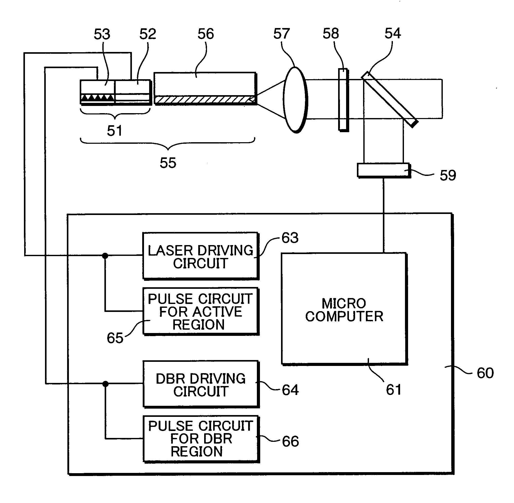
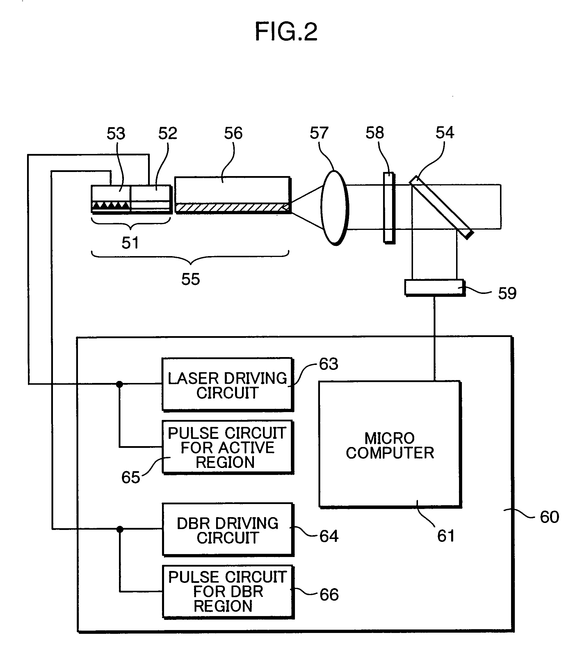
[0054]FIG. 9 is a view schematically showing the configuration of an output control device of the SHG light source in the second embodiment. The output control device comprises a semiconductor laser (triple-electrode LD) 74 having an active region 75, a DBR region 77, ...


PUM


Abstract

In a display device that displays a video by scanning coherent light across a screen, modulation at high speeds and gradation are necessary for a coherent light source. An oscillation wavelength of a semiconductor laser outputting the fundamental wave is changed at high speeds through the plasma effect induced by applying a pulse current to the coherent light source. A change of the wavelength causes the output of a higher harmonic generated in a light wavelength conversion element to change, and gradation is produced using such a change.

Description

TECHNICAL FIELD [0001] The present invention relates to a coherent light source using a wavelength conversion element, a control method thereof, and a display device and a laser display using the same. BACKGROUND ART [0002]FIG. 11 schematically shows the configuration of a laser display 100 as an example of a display device of this kind in the related art. Referring to the drawing, beams of coherent light from laser light sources 101a through 101c of three colors, RGB, undergo intensity modulation, respectively, in light modulators 106a through 106c according to an input video signal, and are then multiplexed on dichroic mirrors 102a and 102b. Further, the light is scanned in the horizontal direction by a polygon scanner (polygon mirror) 104 and in the vertical direction by a galvanometer mirror 105, and a two-dimensional image is displayed on a screen 108. [0003] In the display configured in this manner, because beams of light from the respective RGB light sources are beams of mono...

Claims


Application Information

Patent Timeline
IPC IPC(8): H01S3/13H01S3/10H01S5/00H01S5/06H01S5/0625H01S5/0683H04N9/31
CPCH01S5/005H01S5/0078H01S5/0092H01S5/06226H01S5/06253H01S5/06256H01S5/0683H04N9/3129
Inventor YOKOYAMA, TOSHIFUMIYAMAMOTO, KAZUHISA
Owner PANASONIC CORP
Why Eureka
Try Eureka