System and method for clock recovery in digital video communication

a digital video communication and clock recovery technology, applied in the field of system and method for clock recovery in digital video communication, can solve the problems of clock recovery process degradation, complex and high-cost apparatus, and large amount of audio/video data multiplexing for universal video-on-demand, etc., to achieve low complexity, low computational overhead, and low cost

Active Publication Date: 2006-09-21
STMICROELECTRONICS PVT LTD
View PDF5 Cites 10 Cited by
  • Summary
  • Abstract
  • Description
  • Claims
  • Application Information

AI Technical Summary

Benefits of technology

[0037] In DVB-T operation, irregularity in the arrival of PCR packets at the receiver causes serious problems in synchronization of receiver system clock with that of the transmitter. To overcome this problem, a low complexity, low-cost clock recovery system and method corrects the voltage-controlled oscillator (VCXO) at the receiver end by predicting an average PCR difference value at regular time int

Problems solved by technology

Such universal video-on-demand requires massive amounts of audio/video data multiplexing.
The drawback in the above mentioned system is that the computation involved for clock recovery requires a complex and high cost apparatus.
However, there are several factors that lead to degradation in the clock recovery process.
In DVB-Terrestrial (DVB-T) communication, uncertain arrival of PCR packets at

Method used


Image

  • System and method for clock recovery in digital video communication
  • System and method for clock recovery in digital video communication
  • System and method for clock recovery in digital video communication

Examples


Embodiment Construction

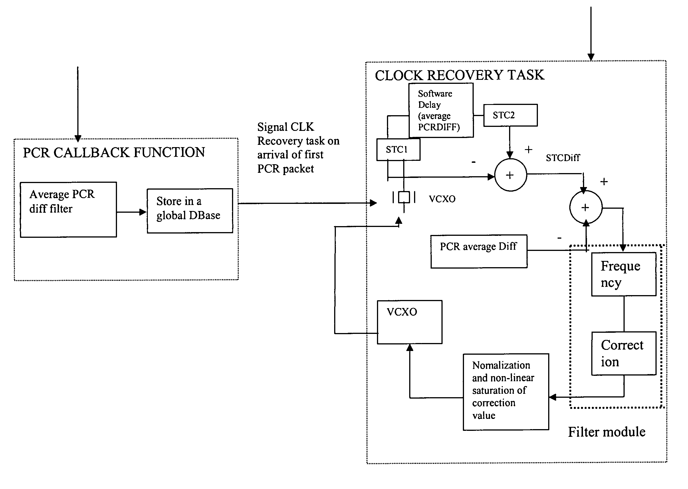
[0046] The block diagram of the clock recovery system in accordance with the instant invention is shown in FIG. 3, wherein it is shown that the PCR delay measurement block generates the input PCR signals for the clock recovery system and measures the delay between the successive PCR packets. The PCR delay block comprises a logic-parsing device for providing selective PCR packet output, wherein the logic-parsing device comprising a demultiplexing logic for priority based injection of PCR packets into the clock recovery system.

[0047] Further, the output from the PCR delay measurement block is fed to a data storage device that comprises buffers or registers for introducing temporal delay in the incoming PCR data stream. The input PCR signal stream is then fed to the PCR average difference filter that computes the average inter-arrival time between the successive PCR packets. The gain factor of the filter is then compensated by coupling the filter output to a coefficient multiplier.

[0...


PUM


Abstract

A system for clock recovery in digital video communication includes a delay measurement block for generating PCR input signals and for continuously determining the time interval between successive PCR input signals. The system also includes a first storage device for generating a first PCR signal corresponding to the time interval between arrival of successive PCR input signals and a PCR inter-arrival time computation filtering device to determine the average time of arrival difference between successive PCR packets. The system further includes an error correction device for minimizing error in the average PCR difference between successive PCR packets, a controlled system clock generator coupled to the output of the error correction device to generate system clock, a second storage device for generating a first system clock output, and a controlled clock period difference computation element for computing the clock period difference between the first and second system clock outputs. The controlled clock period difference computation element is coupled at its output to the error correction device to form a feedback circuit to minimize error between the system clock output and successive PCR differences.

Description

RELATED APPLICATIONS [0001] The present application claims priority from India Patent Application No. 2052 / Del / 2004 filed as a provisional application on Oct. 20, 2004, for which a complete specification was filed on Oct. 14, 2005, both of which documents are incorporated herein in their entireties by this reference. [0002] 1. Field of the Invention [0003] This invention relates to a system and method for clock recovery in digital video communication. [0004] 2. Background of the Invention [0005] In conventional digital video communication systems data is made available to the customers' home television set at the request or demand of the customer. Customers select a channel and enter a code into a box (widely known as set top box) at home, and the program gets delivered. Such universal video-on-demand requires massive amounts of audio / video data multiplexing. This multiplexing is done as per the MPEG2 system standard (13818-1). Each set top box must receive data and then process it ...

Claims


Application Information

Patent Timeline
IPC IPC(8): H04L27/00
CPCH04N21/4305
Inventor SAHA, KAUSHIKCHAKRABORTY, CHIRANJIBCHATTERJEE, SUBRATA
Owner STMICROELECTRONICS PVT LTD
Why Eureka
Try Eureka