Method and apparatus for generation and transmission of high energy optical pulses for long range measurements

a technology of optical pulses and long-range measurements, applied in the field of sensing systems, can solve the problems of limiting the amount of light that can be launched, attenuating the signal, and poor resolution of temperature and loss measurements, so as to reduce interference, improve the signal averaging process, and increase the pulse repetition rate

Inactive Publication Date: 2006-09-21
SENSORNET
View PDF9 Cites 39 Cited by
  • Summary
  • Abstract
  • Description
  • Claims
  • Application Information

AI Technical Summary

Benefits of technology

[0012] This cleverly exploits the non-linear effects which up to now have been avoided or minimised. After a short transition length all the original light is converted to this new wavelength which is then used to illuminate the remaining length of fibre. One advantage is that it can enable the distance limit to be raised for a given level of sensing accuracy or resolution, since the launch power can be much greater and so returned optical signals returned from greater distances along the fibre can be detected. Another advantage is that it can provide a self-optimisation process because as the distance is increased, the light shifts towards longer wavelengths, which incur lower fibre scatter losses. The electromagnetic signals can be optical signals or other wavelengths. The shape refers to the shape on a power vs time graph for example. The peak power is one part of the shape which has a strong influence on controlling where the SRS wavelength conversion takes place but the pulse width and characteristics of the transmission medium also play a part.
[0063] Other aspects also include the use of a switch to send the pulses to at least two sensing fibres and or to both ends of the sensing fibres. A means for calibration the transmission wavelength and modal dependence of the switch, such as by using at least one reference section at a known temperature, may also be used to improve the accuracy of the temperature measurements between different sensing fibres.

Problems solved by technology

As the fibre length increases, the resolutions of the temperature and loss measurements become poorer.
This is because there are causes of loss in an optical fibre that attenuate the signal.
An obvious solution to this problem is to launch more light into the fibre to compensate for the losses but there is a limit to how much light may be launched.
This is because when high power light is sent down a fibre, there are non-linear effects that become significant as the length of the fibre is increased.
The most problematic of these is the stimulated Raman effect.
This approach is restrictive, however, as it requires the technique be used in potentially expensive, specialised fibres.
This approach will also not allow the system to be used on normal optical fibres that may have previously been installed.
Another cause of poorer resolution of the temperature and loss measurements as the fibre length increases is the longer round trip delay for each pulse.
It is normally only possible to usefully have one pulse in the fibre at any time as otherwise it would not be possible to determine where the returning signal was generated (the backscattered signals from the multiple pulses would overlap).
As typically many averages are required to measure the signal with a reasonable accuracy, this necessary reduction in pulse repetition rate means that the measurements become less accurate as the sensing length is increased.
However, the SRS threshold cannot be raised indefinitely and the pulse repetition rate is still limited by the round-trip time of the pulse through the whole length of fibre.
Another source of error is differential loss at different wavelengths.
This is a property of most common types of fibre and is a source of error because the temperature calculation involves determining a ratio of powers of the returning light at different wavelengths.
As the distance of the desired measurement point along the fibre increases, this source of error becomes more significant.
This can cancel the differential loss error, but it would be difficult or expensive to ensure the two sources are sufficiently similar over their lifetime that other errors are not introduced.
The single tunable source is less practical because it is difficult to tune and pulse such sources.

Method used


Image

  • Method and apparatus for generation and transmission of high energy optical pulses for long range measurements
  • Method and apparatus for generation and transmission of high energy optical pulses for long range measurements
  • Method and apparatus for generation and transmission of high energy optical pulses for long range measurements

Examples


Embodiment Construction
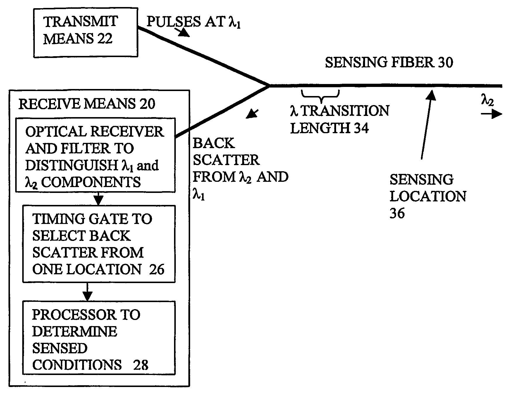
FIG. 1

[0074]FIG. 1 shows an embodiment of the invention. A transmitting means 22 is coupled to a sensing fibre 30 and sends pulses along the fibre at λ1. The pulses are of sufficient power that SRS builds up along the fibre and causes wavelength conversion during the λ transition length 34. The backscatter from all points of the sensing fibre is separated from the forward going light using conventional techniques, and fed to receiving means 20. This backscatter has Raman Stokes, Raman anti Stokes and Rayleigh components derived from both forward going wavelengths λ1 and λ2.

[0075] The receiving means has an overall purpose of outputting a sensed value or values of the conditions at a sensing location 36 at a given distance along the sensing fibre derived from the backscattered signal. This involves distinguishing the useful parts of the backscatter light and calculating the sensed value. In the example shown, there is an optical receiver 24 with an optional filter for separating the...


PUM

PropertyMeasurementUnit
distancesaaaaaaaaaa
distancesaaaaaaaaaa
wavelengthsaaaaaaaaaa

Abstract

A method and apparatus for generating and transmitting high energy optical pulses are described. Distributed temperature sensors usually use Raman scattering in optical fibres as the means to determine the temperature. Here, light from a laser source is sent down a fibre and the small amount of light that is scattered back towards the source is analysed. As the fibre length increases, the resolutions of the temperature and loss measurements become poorer. This is because losses in an optical fibre attenuate the signal. An obvious solution to this problem is to launch more light into the fibre to compensate for the losses but stimulated Raman scattering limits how much light may be launched. The present invention solves this problem by using a pulse conversion method to maximise the resultant pulse energy while the power is kept below SRS threshold.

Description

FIELD OF THE INVENTION [0001] The present invention relates to sensing systems, to a method and apparatus for generating and transmitting high energy light pulses for sensing, particularly for long range measurements and, in particular, for the distributed optical fibre measurement of measurands such as temperature and loss over long distances, and to transmitters for such systems, to receivers for such systems, and to apparatus for, and methods of, generating pulses for such purposes. BACKGROUND [0002] There is a requirement in industry for the measurement of temperature at all points over long distances. Typical uses are for monitoring long cables and pipelines. As these structures may be very long, there is a need for a sensing system that operates over very long distances. There is a requirement in communications and sensing to measure the loss along optical fibres. As these fibres may be very long, there is a need for a loss measurement system that operates over very long dista...

Claims


Application Information

Patent Timeline
Patent Type & Authority Applications(United States)
IPC IPC(8): H04J14/00G01D5/26G01D5/353G01K11/32
CPCG01D5/35364G01K11/32
Inventor FARHADIROUSHAN, MAHMOUDPARKER, TOM RICHARDKEAN, PETER NEIL
Owner SENSORNET
Why Eureka
Try Eureka