
Laminated magnetic thin films with sublayers for magnetic recording

Inactive Publication Date: 2006-09-21
HITACHI GLOBAL STORAGE TECH NETHERLANDS BV
View PDF30 Cites 7 Cited by
  • Summary
  • Abstract
  • Description
  • Claims
  • Application Information

AI Technical Summary

Benefits of technology

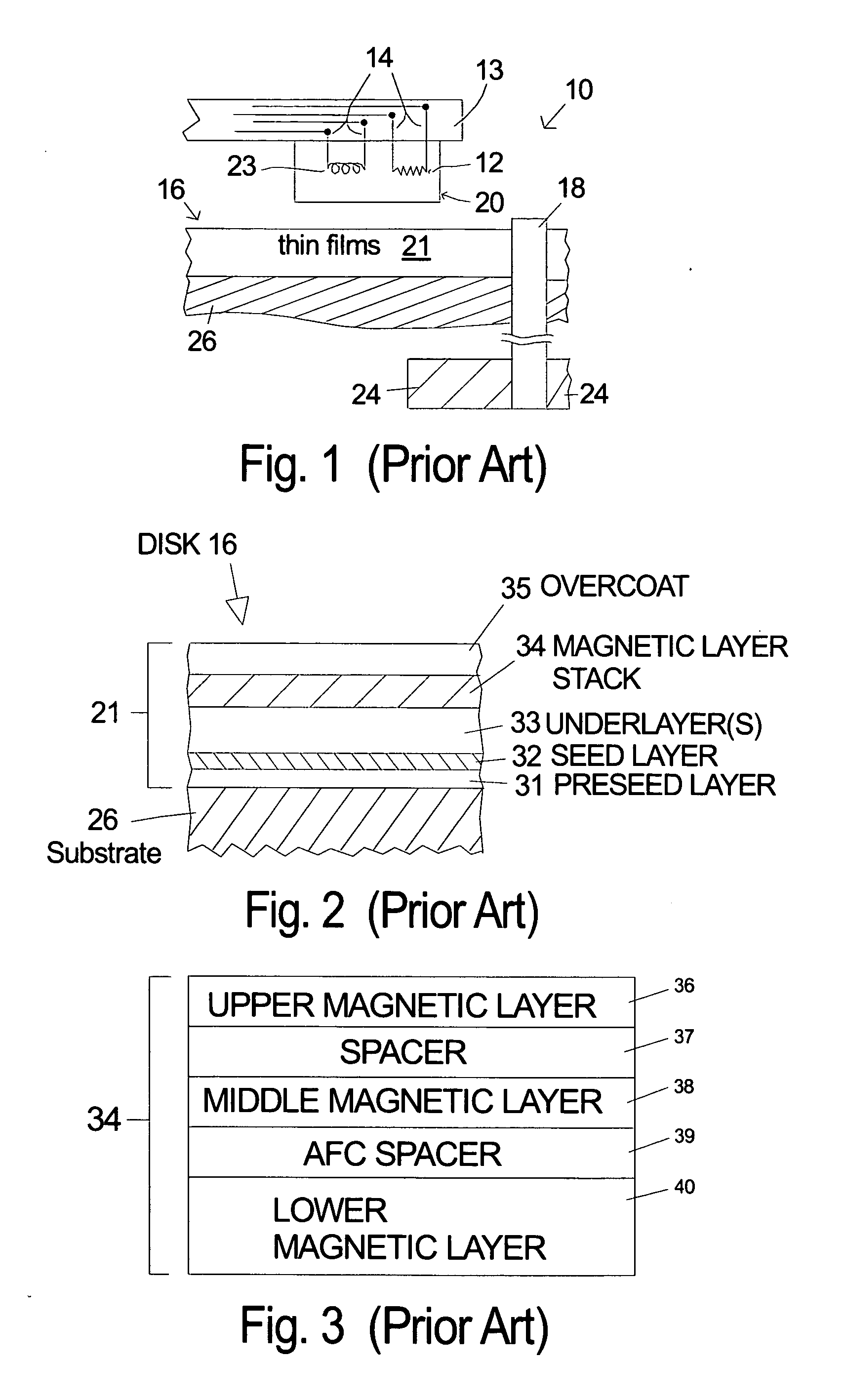
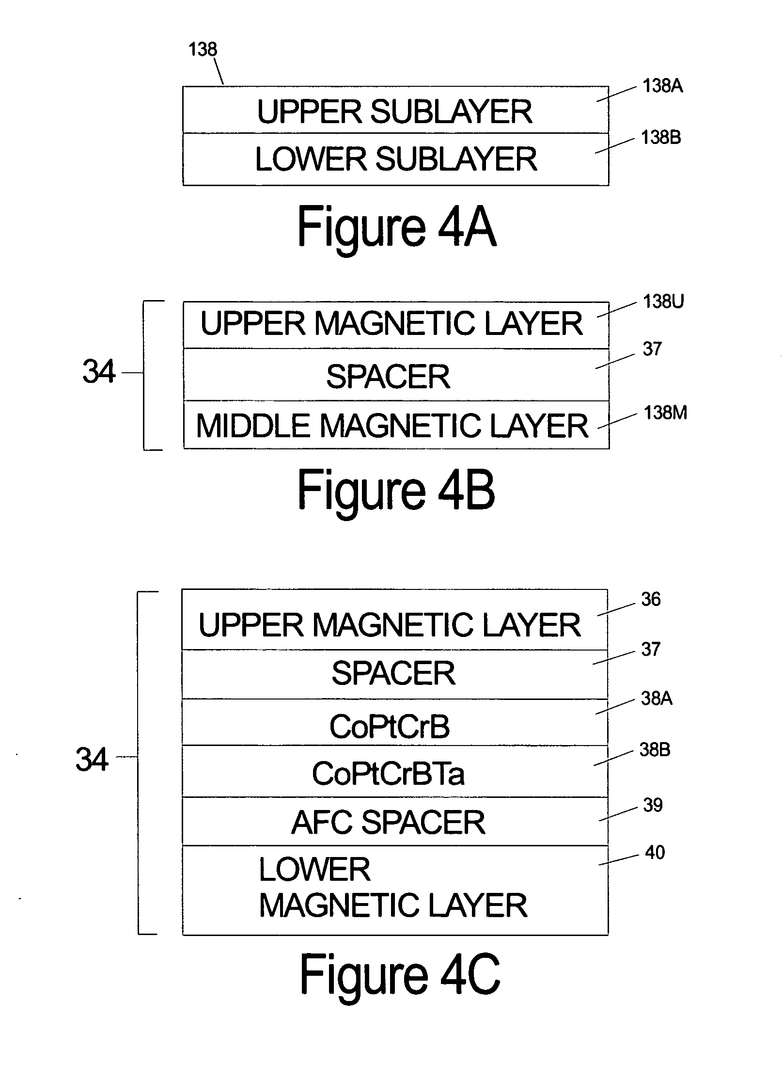
[0024] The upper sublayer is a higher moment alloy with high intrinsic coercivity. The sublayers are strongly coupled together because they are in direct contact and magnetically act as one layer with the effective intrinsic coercivity being the average of the two sublayers. Therefore, the H0 of this composite middle layer can be readily adjusted by simply changing the thickness ratio of the two layers. Furthermore, the H0 can be changed more readily and with much finer control over the value than is possible by changing the alloy composition as is done in the prior art. An embodiment of the invention includes the laminated magnetic layer structure described above with an antiferromagnetically coupled lower magnetic layer.

Problems solved by technology

At some point, as V decreases, the stored magnetic information will no longer be stable under the storage device's operating conditions.
However, the increase in Ku is limited by the point where the coercivity Hc, which is approximately equal to Ku / Mr, becomes too great to be written by a practical write heads.
A similar approach is to reduce the Mr of the magnetic layer for a fixed layer thickness, but this is also limited by the coercivity that can be written.
However, this approach has been shown to be deleterious to the intrinsic signal-to-noise ratio (S0NR) of the magnetic layer.

Method used


Image

  • Laminated magnetic thin films with sublayers for magnetic recording
  • Laminated magnetic thin films with sublayers for magnetic recording
  • Laminated magnetic thin films with sublayers for magnetic recording

Examples


second embodiment

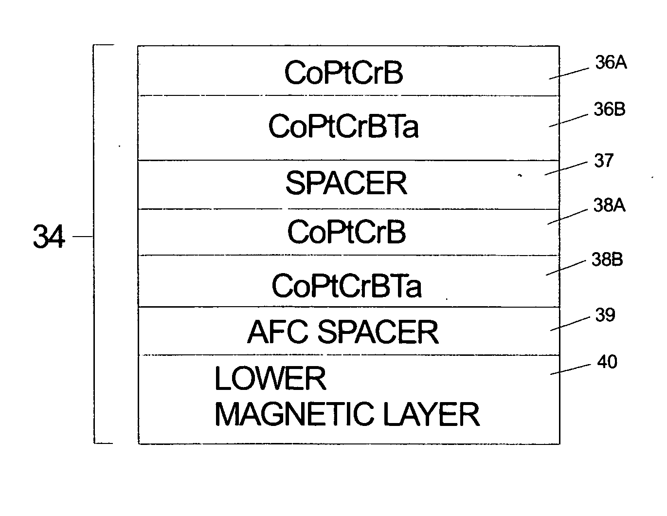
[0059]FIG. 7 is an illustration of a laminated, antiferromagnetically coupled magnetic layer stack for a magnetic thin film disk according to the invention. In the embodiment shown the upper ferromagnetic layer has been replaced by the two sublayers 36A, 36B according to the invention. The composition and principles stated above for the sublayers also apply in this embodiment.

third embodiment

[0060]FIG. 8 is an illustration of a laminated, antiferromagnetically coupled magnetic layer stack for a magnetic thin film disk according to the invention. In this embodiment the upper ferromagnetic layer has been replaced by the two sublayers 36A, 36B according to the invention and the middle ferromagnetic layer has been replaced by the two sublayers 38A, 38B according to the invention. The composition and principles stated above for the sublayers also apply in this embodiment.

[0061] The thin film structures described above can be formed using standard sputtering techniques. The films are sequentially sputter deposited with each film being deposited on the previous film. The atomic percent compositions given above are given without regard for the small amounts of contamination that invariably exist in sputtered thin films as is well known to those skilled in the art. The invention has been described with respect to particular embodiments, but other uses and applications for the fe...


PUM


Abstract

The invention uses an upper and lower sublayer in at least one magnetic layer of a laminated magnetic layer structure that includes a spacer layer that substantially decouples the magnetic layers in a magnetic recording medium. The lower sublayer has a lower boron content than the upper sublayer and a preferred embodiment is CoPtCrBTa. The upper sublayer is deposited onto the lower sublayer and is preferably CoPtCrB with a higher boron content than the lower sublayer. The composition of the lower sublayer gives it a very low moment with low intrinsic coercivity which would not be useful as a recording layer on its own. The upper sublayer is a higher moment alloy with high intrinsic coercivity. An embodiment of the invention includes a laminated magnetic layer structure which is antiferromagnetically coupled to a lower ferromagnetic layer.

Description

RELATED APPLICATIONS [0001] Co-pending, commonly assigned application bearing Ser. No. 10 / 628011 filed on Jun. 11, 2003 describes a laminated antiferromagnetically coupled magnetic recording medium with three magnetic layers separated by two nonmagnetic spacer layers with the middle and bottom layers being antiferromagnetically coupled, and the upper magnetic layer having a higher magnetic anisotropy than the middle magnetic layer. The magnetic anisotropy can be adjusted by primarily by changing the platinum content versus the cobalt content of a cobalt based magnetic alloy such as CoPtCr or CoPtCrB. The magnetization can be adjusted by altering the chromium and / or the boron content versus the cobalt content. Lowering the chromium content and increasing the cobalt content increases the magnetization. [0002] Co-pending, commonly assigned application bearing Ser. No. 10 / 931642 filed on Aug. 8, 2004 describes a laminated antiferromagnetically coupled magnetic recording medium with an A...

Claims


Application Information

Patent Timeline
IPC IPC(8): G11B5/66
CPCG11B5/656G11B5/66G11B5/678G11B5/672
Inventor DO, HOA VANFULLERTON, ERIC EDWARDMARGULIES, DAVID THOMASSUPPER, NATACHA FREDERIQUE
Owner HITACHI GLOBAL STORAGE TECH NETHERLANDS BV
Learn More