Fluid delivery systems, devices and methods for delivery of fluids

a technology of fluid delivery system and fluid delivery method, which is applied in the field of fluid delivery system, can solve the problems of high cost of contrast, time-consuming and laborious reloading of syringes, and waste of resources

Inactive Publication Date: 2006-09-21
MEDRAD INC.
View PDF18 Cites 53 Cited by
  • Summary
  • Abstract
  • Description
  • Claims
  • Application Information

AI Technical Summary

Benefits of technology

[0033] In an additional aspect, the present invention provides a fluid delivery device, including: at least one inlet connectible to a fluid supply and at least two resilient pressurizing chambers in fluid connection with the at least one inlet. Each of the pressurizing chambers is formed from a flexible material that can be compressed to pressurize fluid within the pressurizing chamber. The fluid delivery system further includes an inlet valve in fluid connection with each of the pressurizing chambers between the storage container and the pressurizing chamber. The inlet valve is operable to allow fluid to enter the pressurizing chamber from the storage container but to prevent fluid from flowing from the pressurizing chamber into the storage container. A common outlet is in fluid connection with the pressurizing chambers. An outlet valve is in fluid connection with each of the pressurizing chambers between the pressurizing chamber and the outlet. The outlet valve is operable to allow fluid to enter the outlet from the pressurizing chamber but to prevent fluid from flowing from the outlet into the pressurizing chamber.

Problems solved by technology

In that regard, contrast is typically very expensive.
Time consuming procedures are required to reload the syringe if more contrast is required than originally calculated.
On the other hand, expensive waste results if only a portion of a filled syringe is injected.
The inventory of contrast containers required under the current system increases costs and regulatory burdens throughout the contrast media supplier-consumer chain.
Waste also occurs, for example, in that case that a prefilled syringe includes insufficient fluid, resulting in termination of a procedure or use of only a portion of a second prefilled syringe.
Although continuous pumping systems such as disclosed in U.S. Pat. Nos. 5,916,197 and 6,197,000 can eliminate many of the problems associated with current injection practices, a number of problems persist.
For example, there is a risk of contamination by operating personnel when removable fluid connections are made or broken (such as the fluid connection between a fluid source and the pumping mechanism of the pumping system).
Making such fluid connections also requires use of valuable and limited operator time.
Furthermore, required operator tasks introduce the potential for human error.

Method used


Image

  • Fluid delivery systems, devices and methods for delivery of fluids
  • Fluid delivery systems, devices and methods for delivery of fluids
  • Fluid delivery systems, devices and methods for delivery of fluids

Examples


Embodiment Construction

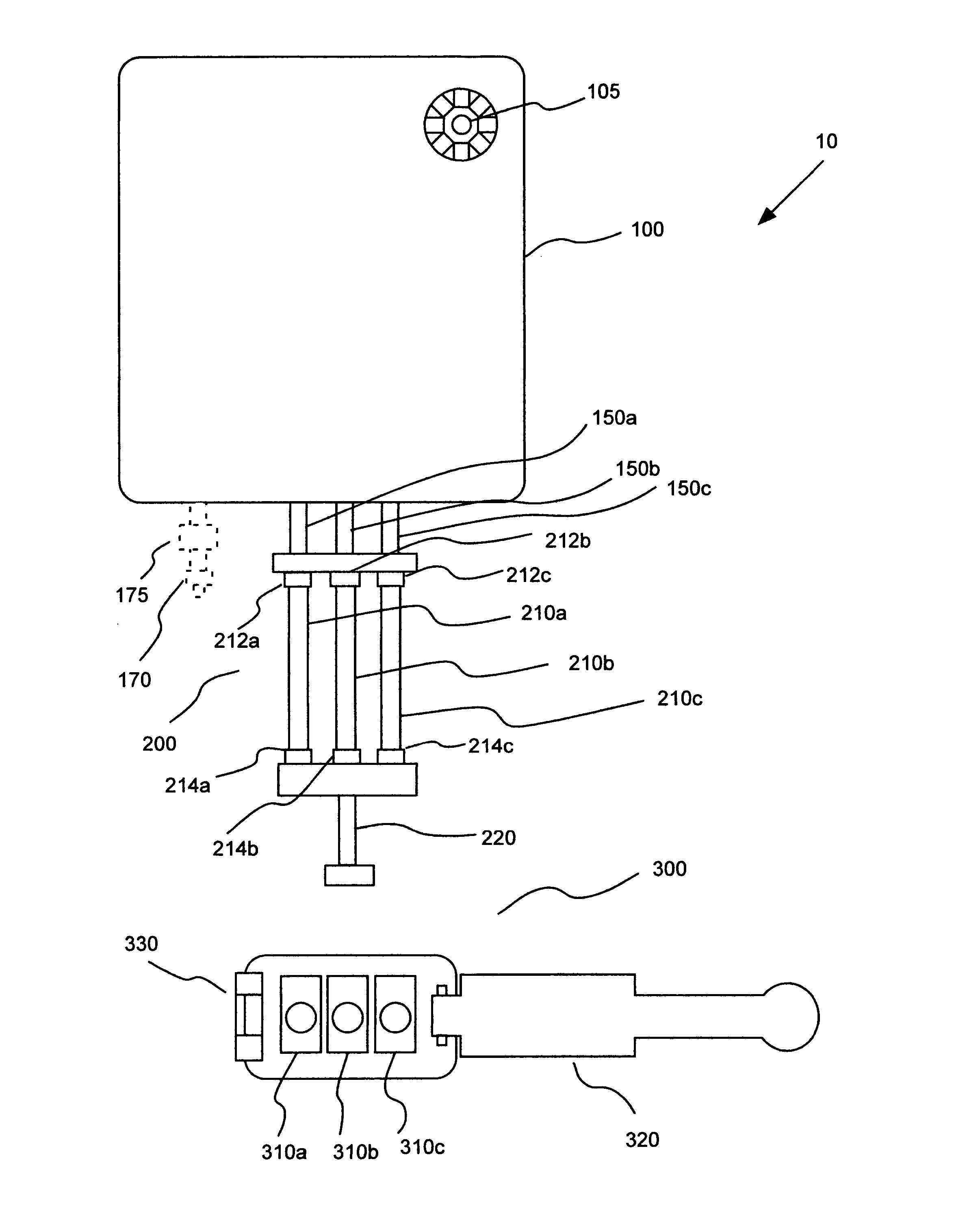
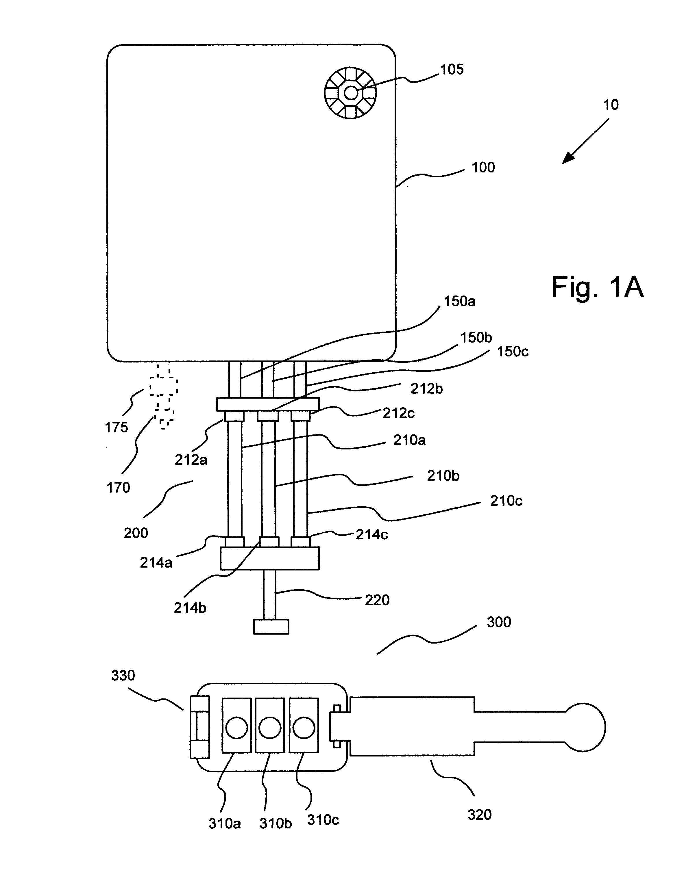
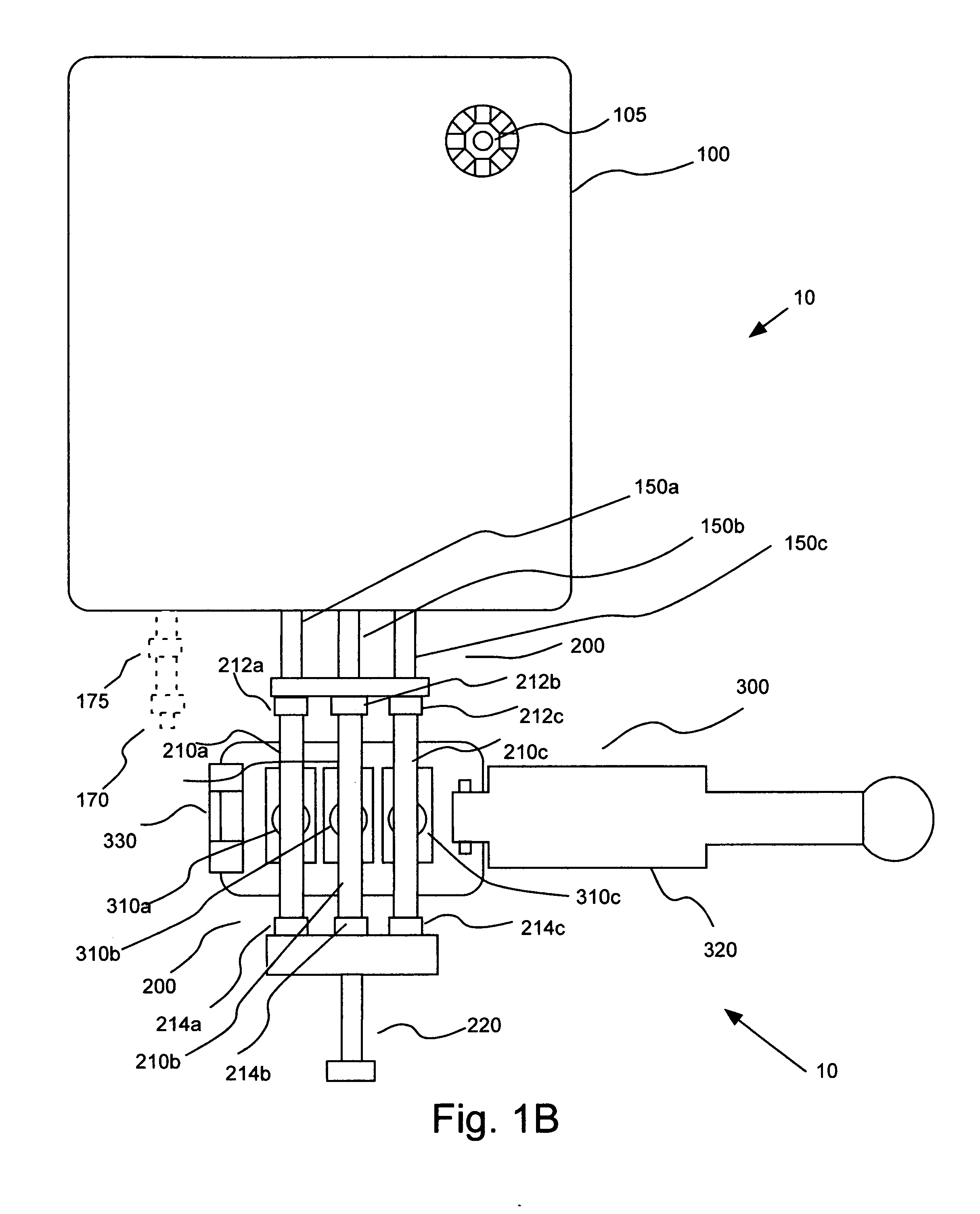
[0054] In general, the present invention provides fluid delivery systems that can be used to inject one or more fluids into one or more patients. FIGS. 1A through 1D illustrate an embodiment of a fluid delivery system 10 of the present invention in which a fluid container 100 is in operative connection with a continuous pressurizing mechanism 200 including multiple pressurizing chambers. In the embodiment of FIGS. 1A through 1C, pressurizing mechanism 200 includes three pressurizing chambers 210a, 210b and 210c. System 10 further includes an actuator or drive mechanism 300, which operates in connection with pressurizing mechanism 200 to pump fluid from within fluid container 100.

[0055] In one embodiment, each of pressurizing chambers 210a, 210b and 210c is formed from a flexible, resilient material such as a resilient polymeric material (for example, silicone polymer materials, urethane polymer materials and vinyl polymer materials). Drive mechanism 300 includes drive members 310a,...


PUM


Abstract

A fluid delivery system includes a container for fluid to be delivered to a patient, a continuous pump mechanism in non-removable fluid connection with the container, and an outlet in fluid connection with the pump mechanism.

Description

BACKGROUND OF THE INVENTION [0001] The present invention relates generally to fluid delivery systems, to fluid delivery devices and to methods of fluid delivery, and, especially, to fluid delivery systems, devices and method for delivery of medical fluids to a patient. [0002] In many medical procedures, such as drug delivery, it is desirable to inject a fluid into a patient. Likewise, numerous types of contrast media (often referred to simply as contrast) are injected into a patient for many diagnostic and therapeutic imaging procedures. For example, contrast media are used in diagnostic procedures such as X-ray procedures (including, for example, angiography, venography and urography), computed tomography (CT) scanning, magnetic resonance imaging (MRI), and ultrasonic imaging. Contrast media are also used during therapeutic procedures, including, for example, angioplasty and other interventional radiological procedures as well as chemotherapy. Saline is often used as a diluent or f...

Claims


Application Information

Patent Timeline
Patent Type & Authority Applications(United States)
IPC IPC(8): A61M1/00
CPCA61M5/007A61M5/1422A61M2206/22A61M5/002A61M2205/128A61M5/16827A61M5/16881
Inventor RHINEHART, EDWARD J.HACK, DENNIS P.REILLY, DAVID M.KALAFUT, JOHN F.
Owner MEDRAD INC.
Why Eureka
Try Eureka