Device for supplying secondary air in a gas turbine engine

a gas turbine engine and secondary air technology, which is applied in the direction of machines/engines, sustainable transportation, mechanical equipment, etc., can solve the problems of premature degradation of lubricating oil, affecting the overall efficiency of the engine, and preventing adequate cooling, so as to promote energy dissipation, simplify the overall structure, and avoid the effect of affecting the overall efficiency

a gas turbine engine and secondary air technology, which is applied in the direction of machines/engines, sustainable transportation, mechanical equipment, etc., can solve the problems of premature degradation of lubricating oil, affecting the overall efficiency of the engine, and preventing adequate cooling, so as to promote energy dissipation, simplify the overall structure, and avoid the effect of affecting the overall efficiency

US20060213202A1Inactive Publication Date: 2006-09-28HONDA MOTOR CO LTD

Image

  • Device for supplying secondary air in a gas turbine engine
  • Device for supplying secondary air in a gas turbine engine
  • Device for supplying secondary air in a gas turbine engine

Examples


Embodiment Construction

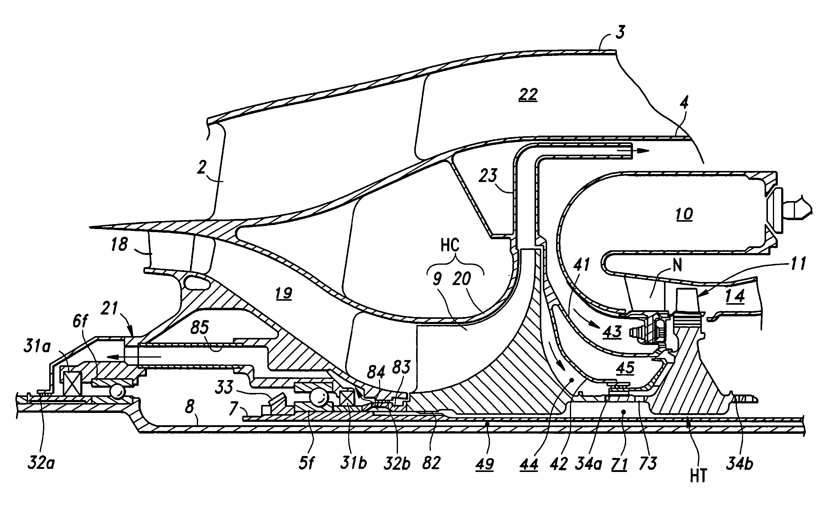
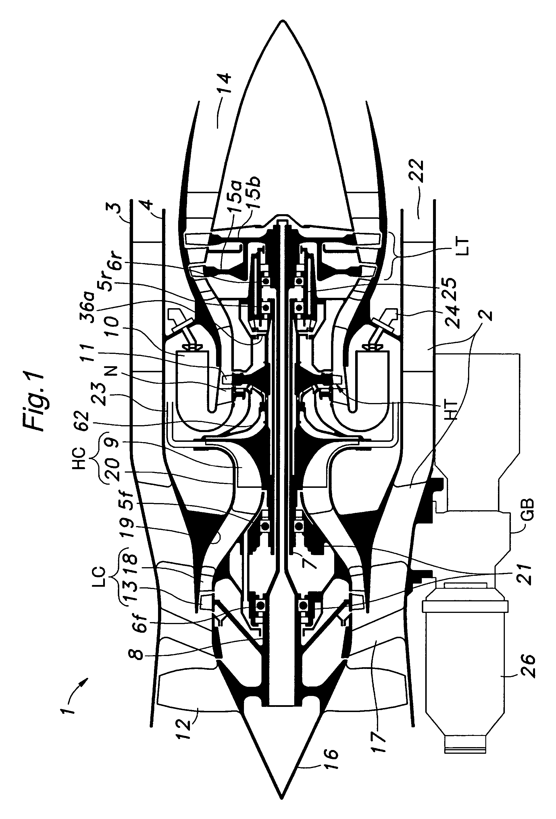
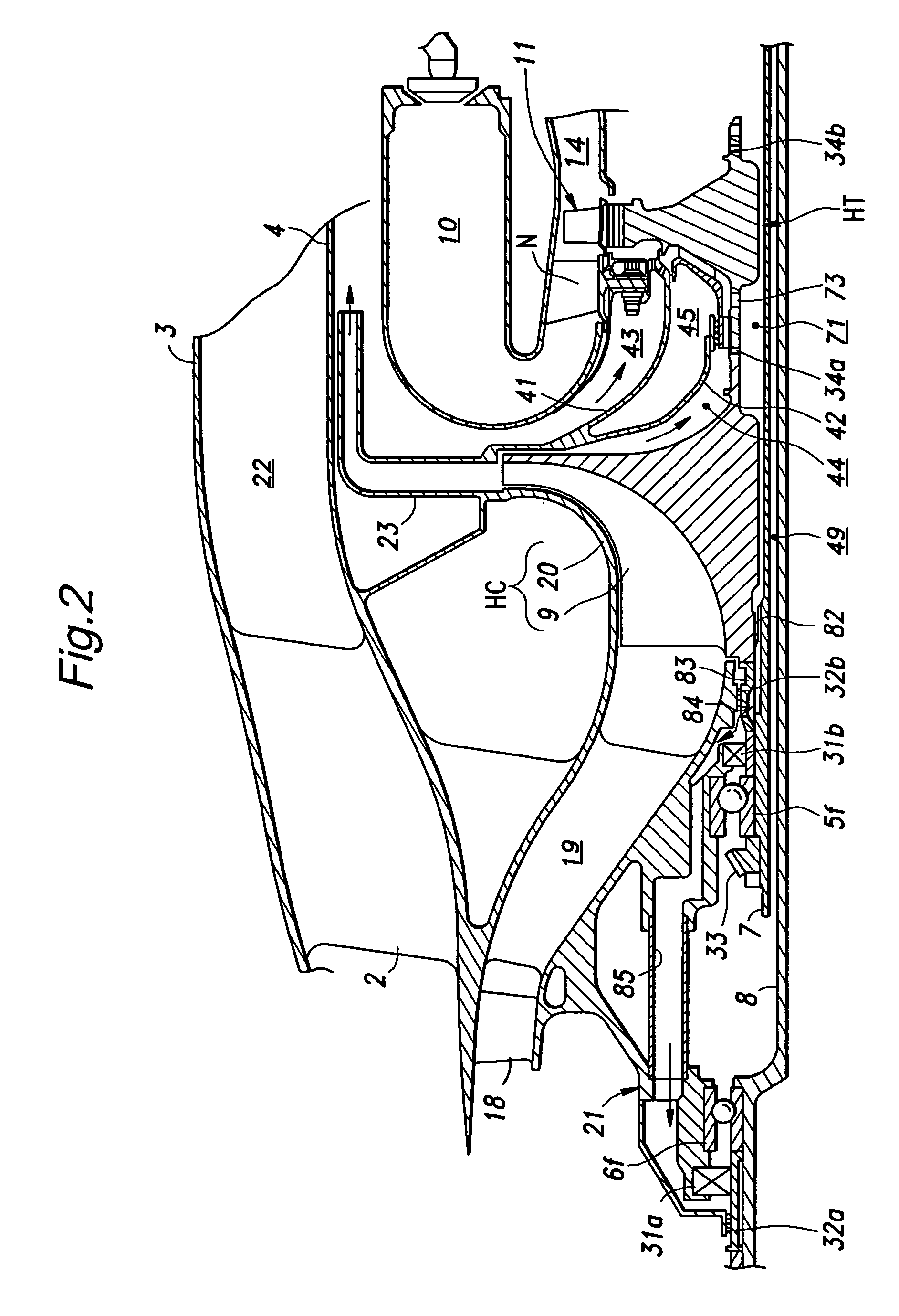
[0023]FIG. 1 is a schematic view of a multiple shaft bypass jet engine embodying the present invention. This engine 1 comprises an outer casing 3 and an inner casing 4 consisting of coaxially arranged cylindrical members joined to each other by struts 2, and an outer shaft 7 and an inner shaft 8 consisting of coaxially arranged hollow shafts centrally supported in the casings by independent bearings 5f, 5r, 6f and 6r.

[0024] The outer shaft 7 has a front end (left end in the drawing) integrally carrying an impeller wheel 9 of a high pressure centrifugal compressor HC, and a rear end (right end in the drawing) integrally carrying a high pressure turbine wheel 11 of a high pressure turbine HT provided adjacent to nozzles N of counter-flow combustion chambers 10.

[0025] The inner shaft 8 has a front end integrally carrying a front fan 12 and a compressor wheel 13 supporting rotor vanes for a low pressure axial flow compressor LC immediately behind the front fan 12, and a rear end integ...


PUM


Abstract

In a device for supplying secondary air in a gas turbine engine provided with an inner shaft (8) and a hollow outer shaft (7) coaxially nested with each other, a seal air introduction passage (71, 85, 88) is defined inside the engine for introducing a part of high pressure air drawn from a high pressure compressor into a seal section provided in each of the bearing boxes for supporting the inner and outer shafts; and a swirl air cooling turbine (59) is provided in the seal air introduction passage and attached to a part attached to the outer shaft in a rotationally fast manner. The swirl air cooling turbine (59) is formed around a section of the outer shaft intermediate between the high pressure compressor and the high pressure turbine, the swirl air cooling turbine including a spiral flow path extending in a substantially cylindrical plane coaxial with the outer shaft. Because the high pressure swirl air is cooled by the swirl air cooling turbine provided in a radially central part, the energy of the swirl air is effectively expended, and this prevents the generation of a stagnation zone. Thereby, the secondary air can be favorably cooled before it is forwarded to the user such as the bearing boxes without causing an undue rise in the pressure of the impeller back chamber.

Description

TECHNICAL FIELD [0001] The present invention relates to a device for supplying secondary air in a gas turbine engine. BACKGROUND OF THE INVENTION [0002] In a certain conventional gas turbine engine, an inner shaft supporting a low pressure compressor impeller wheel and a low pressure turbine wheel and an outer shaft supporting a high pressure compressor impeller wheel and a high pressure turbine wheel typically consist of hollow shafts which are coaxially nested with each other. Such a gas turbine engine is disclosed in WO98 / 28521 A1. According to the conventional gas turbine engine disclosed in this international patent publication, the outer and inner shafts are supported by separate bearings at their front and rear ends, and each bearing is lubricated by a forced lubrication system which blows lubricating oil fed by a pump to the bearing. [0003] In such a forced lubricating system, to positively prevent the lubricating oil from leaking out of the bearing boxes provided in the fro...

Claims


Application Information

Patent Timeline
28 Sep 2006
Publication
US20060213202A1
IPC
F02C6/04
CPC
F01D5/082; F01D11/04; F02C6/08; Y02T50/671; Y02T50/676; Y02T50/60
Inventors
FUKUTANI, MASAYUKI