Valve lifter and method of manufacturing same

a technology of valve lifter and manufacturing method, which is applied in the direction of valve drive, machine/engine, manufacturing tool, etc., can solve the problems of increasing the number of man-hours required to manufacture the valve lifter, increasing the weight and complexity of the valve lifter assembly, and degrading the ability of the valve lifter to follow the valve opening and closing in high-speed operations. , to achieve the effect of reducing the weight of the valve lifter, improving lubrication properties, and reducing the weight ratio

Active Publication Date: 2006-09-28
HONDA MOTOR CO LTD
View PDF4 Cites 3 Cited by
  • Summary
  • Abstract
  • Description
  • Claims
  • Application Information

AI Technical Summary

Benefits of technology

[0017] According to the first aspect of the present invention, a valve lifter includes a sliding surface, on which a cam slides repeatedly during engine operation. The sliding surface is integrally formed as an upper surface of a body of the valve lifter. The invention is characterized in that the integrally formed sliding surface has a concave shape. Accordingly, lubricating oil can be retained on the cam-contacting sliding surface, to improve lubrication properties between the valve lifter and the cam. Moreover, special additional structural components are not required, therefore, the structure of the valve lifter is simplified. Accordingly, it is possible to reduce the weight of the valve lifter and reduce the manufacturing cost thereof.
[0018] According to the second aspect of the present invention, in addition to the first aspect, the above concave shape has a maximum depth of not more than 20 μm. When the depth is greater than 20 μm, the sliding surface only comes into contact with the outer peripheral edge of the cam, and uneven wear can occur. When the depth is not larger than 20 μm, it is possible to prevent the sliding surface from coming into contact only with the outer peripheral edge of the cam, whereby uneven wear is suppressed.
[0019] Furthermore, according to the third aspect of the present invention, in addition to that of the first aspect, the valve lifter is formed of titanium alloy. Accordingly, compared with a valve lifter made of a harder metal, it is possible to distribute the contact between the valve lifter and the cam by taking advantage of the elastic characteristics of the titanium alloy, which has a relatively small Young's modulus, whereby uneven wear is suppressed.
[0020] The Young's modulus of titanium is smaller than that of steel. Accordingly, when pressure applied to the sliding surface, on which the cam slides, increases, the valve lifter is elastically deformed to increase an area which comes into contact with the cam. Load is therefore received over a wider area, so that an increase in pressure on the sliding surface is suppressed. The concave sliding surface of the valve lifter, formed of titanium alloy, stabilizes rotation of the valve lifter and holds lubricating oil on the sliding surface. Moreover, the resistance to wear at the outer periphery of the sliding surface is maintained.
[0021] According to the fourth aspect of the present invention, a method of manufacturing a valve lifter is provided. The valve lifter is formed of titanium alloy and includes a sliding surface, on which a cam slides, that is integrally formed as an upper surface of a lifter body of the valve lifter. In the method of manufacture, the entire body of the valve lifter may be subjected to an oxidation treatment. The method includes the steps of: orienting the valve lifter such that the sliding surface, on which the cam slides, is facing upwardly, and performing the oxidation treatment for the valve lifter. As a result of the oxidation treatment, the sliding surface of the valve lifter is formed into a concave shape. In particular, due to heating at high temperature during the oxidation treatment, the upper surface of the valve lifter hangs down, or slumps, relative to the remaining portions of the valve lifter, so as to be slightly depressed in the center part thereof, because of its own weight under the action of gravity, thus forming the concave surface by itself. Thus, the concave cam-contacting sliding surface of the valve lifter can be easily formed, by using the inherent weight of the upper part of the valve lifter, without any special processing. Accordingly, the number of required manufacturing man-hours and manufacturing cost can be reduced.
[0022] According to the fifth aspect of the present invention, in addition to the fourth aspect, a protrusion, for abutting on a tip portion of an intake or exhaust valve directly, or with an inner shim interposed therebetween, is formed in the center of an inner surface of an upper part of the valve lifter. When the protrusion is formed in the center of the inner surface of the upper part of the valve lifter, the upper part is the heaviest at the center, and the center position of the concave portion of the sliding surface can substantially match the center position of the upper part, thus increasing the forming accuracy. Furthermore, changing the shape of the protrusion changes the shape of the concave portion of the sliding surface, whereby the shape of the sliding-surface can be adjusted. Moreover, it is possible to adjust the rigidity of the sliding surface in operation.

Problems solved by technology

However, in this known design, providing the above-described shim in the upper surface of the valve lifer increases the weight and complexity of the valve lifter assembly.
Moreover, the weight increase of the valve lifter increases inertia of the valve lifter, thus degrading an ability of the valve lifter to follow the valve opening and closing in high-speed operations.
Moreover, the number of man-hours required to manufacture the valve lifter is increased, and accordingly, the manufacturing cost increases.
However, on the other hand, there is a problem of lower resistance to wear and scuff in a severe operating situation, since the surface pressure increases in the outer portion which is brought into contact with the cam.
The concave valve lifter, therefore, has not been put into significant effective practical use heretofore.

Method used


Image

  • Valve lifter and method of manufacturing same
  • Valve lifter and method of manufacturing same
  • Valve lifter and method of manufacturing same

Examples


Embodiment Construction

[0034] A selected illustrative embodiment of the invention will now be described in some detail, with reference to FIGS. 1-4. It should be understood that only structures considered necessary for clarifying the present invention are described herein. Other conventional structures, and those of ancillary and auxiliary components of the system, are assumed to be known and understood by those skilled in the art.

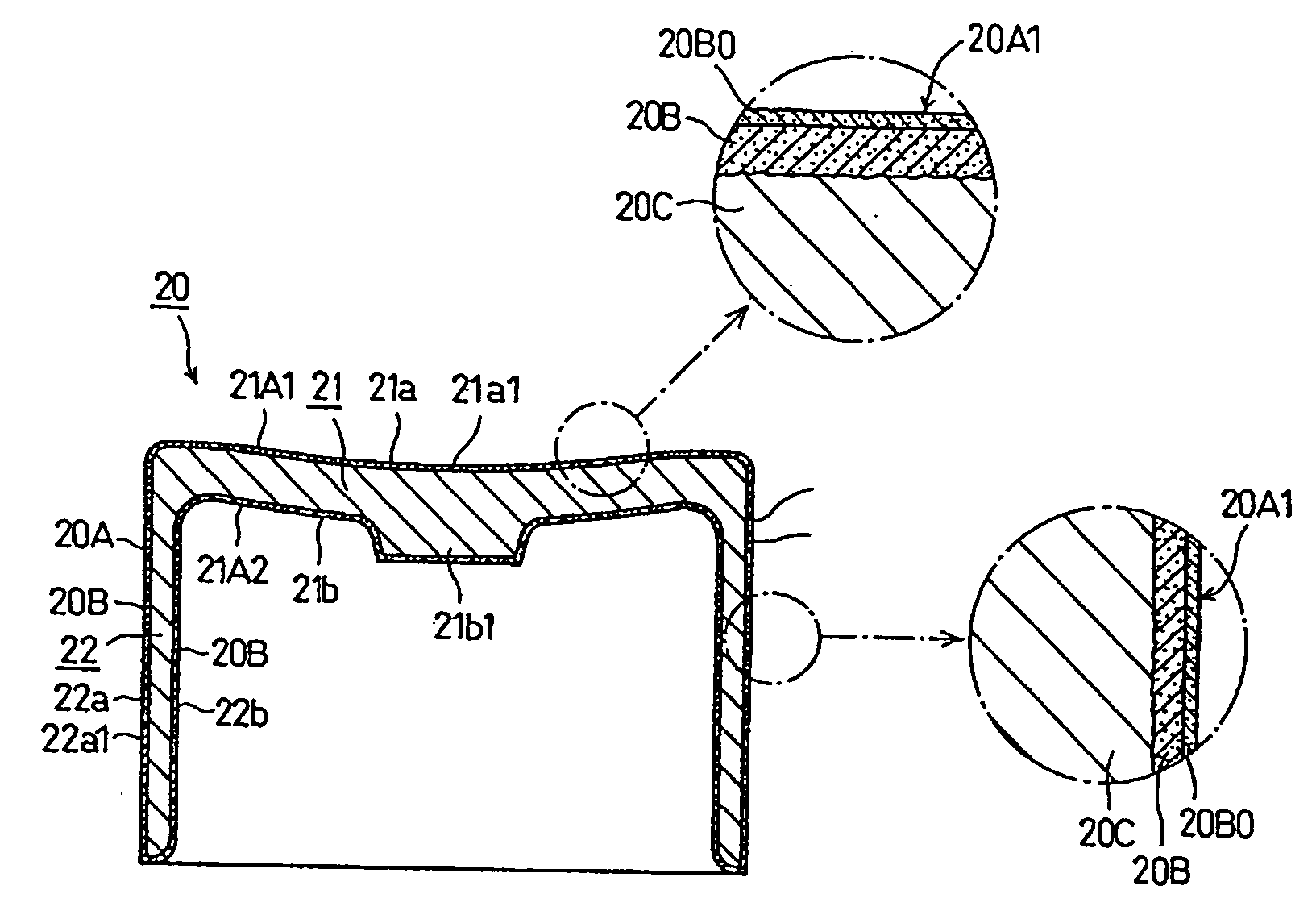
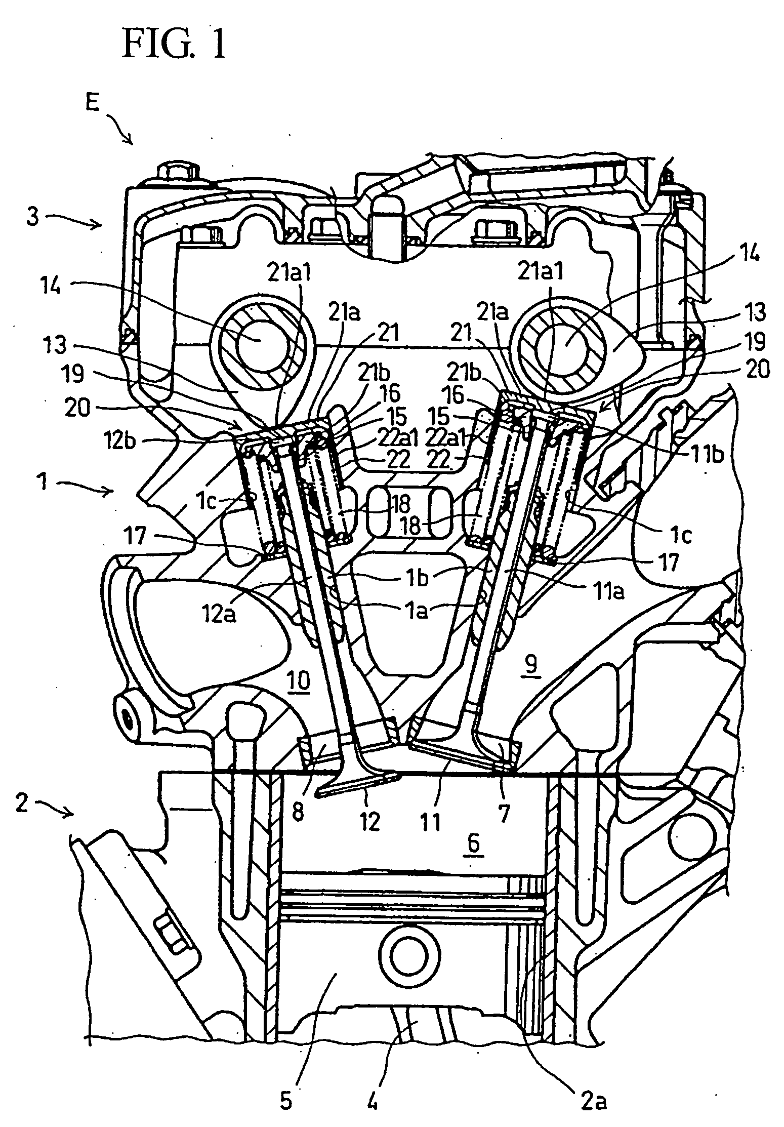
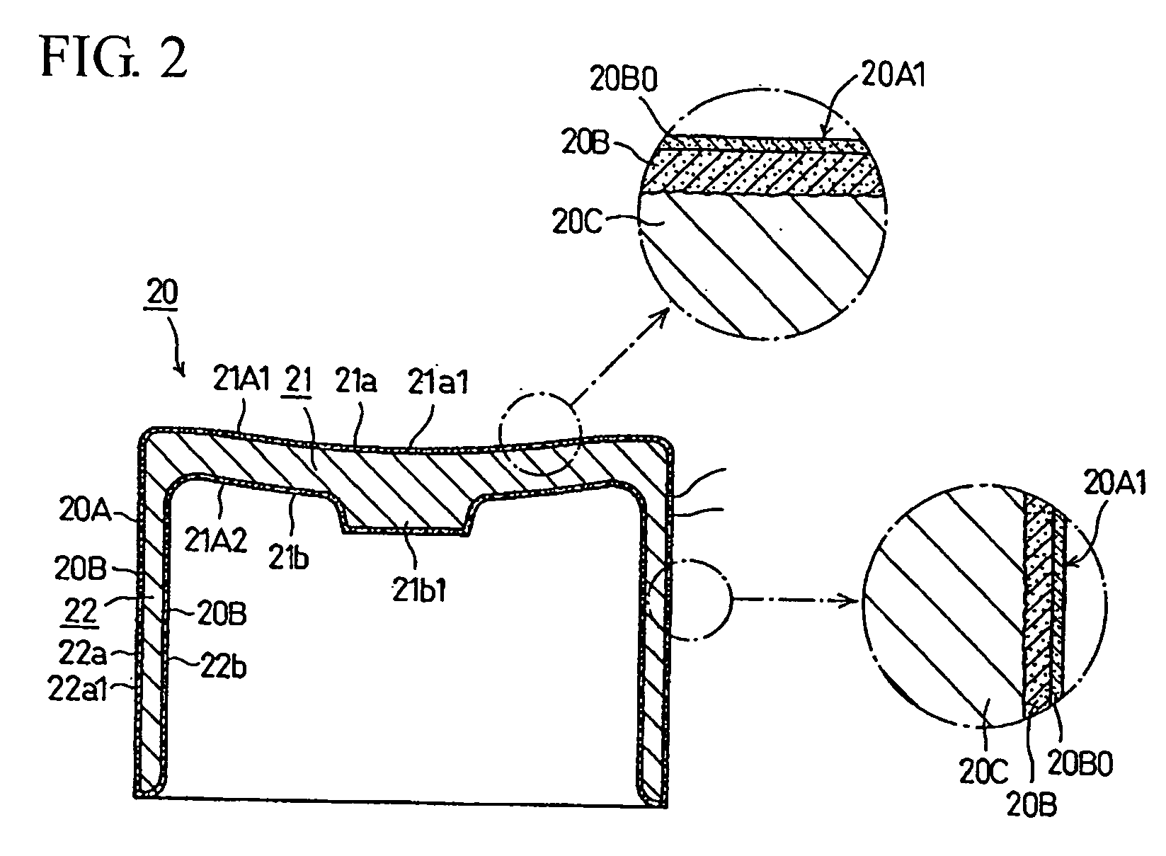
[0035]FIG. 1 is a side-sectional view of a cylinder head 1 of an internal combustion engine and surroundings. The illustrated engine is of a double overhead cam (DOHC) design. The cylinder head 1 includes a valve train using valve lifters 20 according to a selected illustrative embodiment of the present invention. In particular, the valve lifters 20 each have a concave cam-contacting sliding surface 21a1 formed in an upper surface 21 of a lifter body thereof.

[0036] The cylinder head 1 is connected and fixed to an upper part of a cylinder block 2, whose lower part is connected ...


PUM

PropertyMeasurementUnit
depthaaaaaaaaaa
temperatureaaaaaaaaaa
heightaaaaaaaaaa

Abstract

A valve lifter and a method of manufacture thereof is provided in which sliding properties of a cam on a cam-contacting sliding surface in an upper surface of a valve lifter are improved by forming the cam-contacting sliding surface as a concave surface to permit retention of lubricating oil therein. The cam-contacting sliding surface is integrally provided in an outer wall of an upper part of a valve lifter. The cam-contacting sliding surface is formed as a concave surface to provide better retention of the lubricating oil. The concave sliding surface is formed during high temperature oxidation of the valve lifter by permitting the natural slumping down of the upper part due to its own weight under the gravity.

Description

CROSS-REFERENCE TO RELATED APPLICATIONS [0001] The present invention claims priority under 35 USC 119 based on Japanese patent application No. 2005-086142, filed on Mar. 24, 2005. The subject matter of these priority documents is incorporated by reference herein. BACKGROUND OF THE INVENTION [0002] 1. Field of the Invention [0003] The present invention relates to a valve lifter, and to a method of manufacturing the same. Specifically, the present invention relates to a valve lifter, and a method of making the valve lifter, in which a cam-contacting sliding surface is concave in shape, and is formed in an upper surface of the valve lifter. [0004] 2. Description of the Background Art [0005] Valve lifters are generally well known in the art of internal combustion engines, and have been conventionally used for many years. A valve lifter, as a component of a valve train of an internal combustion engine, includes a sliding surface on which a cam slides repeatedly during engine operation. T...

Claims


Application Information

Patent Timeline
Patent Type & Authority Applications(United States)
IPC IPC(8): F01L1/14F01L1/02
CPCF01L1/053F01L1/143F01L1/16Y10T29/49885Y10T29/49298Y10T29/49247Y10T29/49304Y10T29/4998
Inventor HORIMURA, HIROYUKIDOI, KOSUKE
Owner HONDA MOTOR CO LTD
Why Eureka
Try Eureka