

Ceramic igniters
a ceramic igniter and ceramic technology, applied in the field of ceramic igniters, can solve the problems of inherent limitations of batch-type processing in output and cost efficiency, and the current ceramic igniters have suffered from breakage during use, and achieve the effect of enhancing output and cost efficiency and notable mechanical strength
- Summary
- Abstract
- Description
- Claims
- Application Information
AI Technical Summary
Benefits of technology
Problems solved by technology
Method used
Image

Examples
example 1
Igniter Fabrication
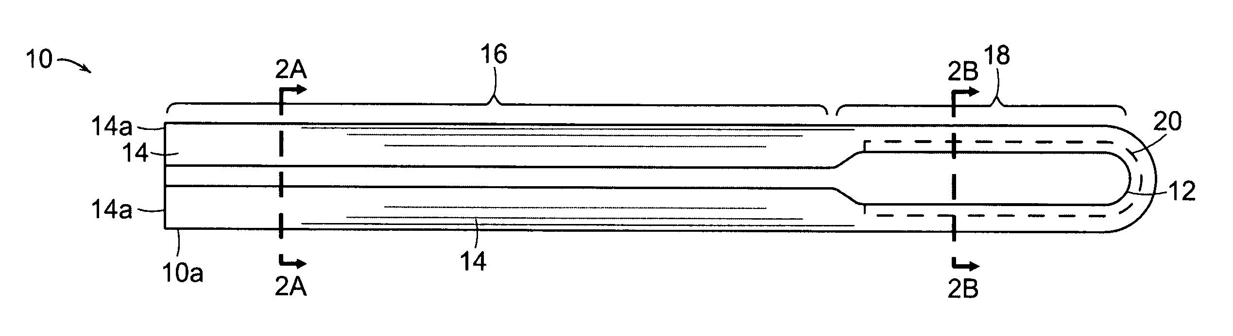
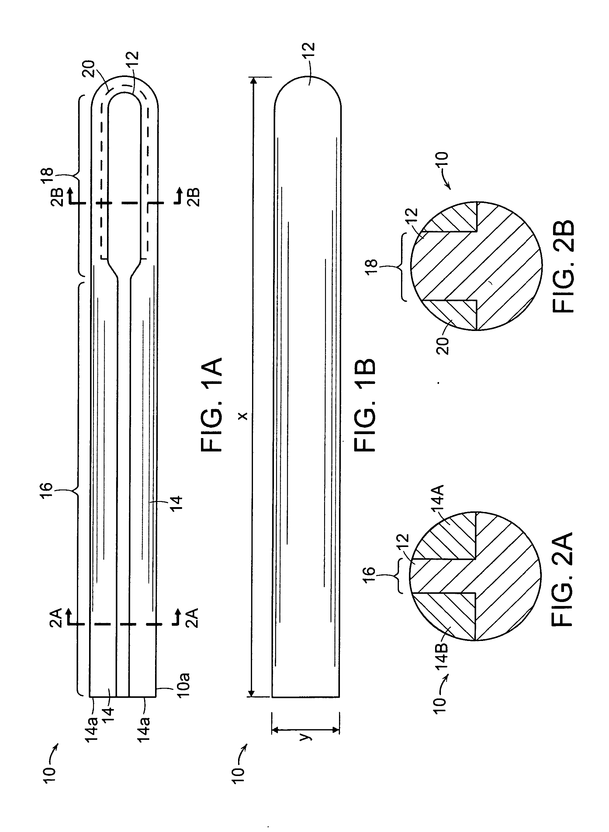
[0067] Powders of a resistive composition (22 vol % MoSi2, remainder Al2O3) and an insulating composition (100 vol % Al2O3) were mixed with an organic bonder (about 6-8 wt % vegetable shortening, 2.4 wt % polystyrene and 2-4 wt % polyethylene) to form two pastes with about 62 vol % solids. The two pastes were loaded into two barrels of a co-injection molder. A first shot filled a half-cylinder shaped cavity with insulating paste forming the supporting base with a fin running along the length of the cylinder. The part was removed from the first cavity, placed in a second cavity and a second shot filled the volume bounded by the first shot and the cavity wall core with the conductive paste. The molded part which forms a hair-pin shaped conductor with insulator separating the two legs. The rod was then partially debindered at room temperature in an organic solvent dissolving out 10 wt % of the added 10-16 wt %. The part was then thermally debindered in flowing inert...
example 2
Additional Igniter Fabrication
[0068] Powders of a resistive composition (22 vol % MoSi2, remainder Al2O3) and an insulating composition (5 vol % SiC, remainder Al2O3) were mixed with an organic bonder (about 6-8 wt % vegetable shortening, 2.4 wt % polystyrene and 2-4 wt % polyethylene) to form two pastes with about 62 vol % solids. The two pastes were loaded into two barrels of a co-injection molder. A first shot filled a half-cylinder shaped cavity with insulating paste forming the supporting base with a fin running along the length of the cylinder. The part was removed from the first cavity, placed in a second cavity and a second shot filled the volume bounded by the first shot and the cavity wall core with the conductive paste. The molded part which forms a hair-pin shaped conductor with insulator separating the two legs. The rod was then partially debindered at room temperature in an organic solvent dissolving out 10 wt % of the added 10-16 wt %. The part was then thermally deb...
example 3
Additional Igniter Fabrication
[0069] Powders of a resistive composition (22 vol % MoSi2, 20 vol % SiC, remainder Al2O3) and an insulating composition (20 vol % SiC, remainder Al2O3) were mixed with about 15 wt % polyvinyl alcohol to form two pastes with about 60 vol % solids. The two pastes were loaded into two barrels of a co-injection molder. A first shot filled a cavity that had an hour-glass shaped cross-section with insulating paste forming the supporting base. The part was removed from the first cavity, placed in a second cavity and a second shot filled the volume bounded by the first shot and the cavity wall core with the conductive paste. The molded part which forms a hair-pin shaped conductor with insulator separating the two legs was then partially debindered in tap water dissolving out 10 wt % of the added 10-16 wt %. The part was then thermally debindered in flowing inert gas (N2) at 500° C. for 24 h to remove the remainder of the residual binder. The debindered part wa...
PUM
| Property | Measurement | Unit |
|---|---|---|
| Electric potential / voltage | aaaaa | aaaaa |
| Electric potential / voltage | aaaaa | aaaaa |
| Electric potential / voltage | aaaaa | aaaaa |
Abstract
Description
Claims
Application Information