Technological machinery for production of polarizers

a technology of polarizers and machinery, applied in the direction of polarising elements, instruments, coatings, etc., can solve the problems of compromising the quality of sealing, difficulty in removing polarizers from the sites of glued junctions, and additional expenditures for display fabrication, so as to enhance the effect of molecular orientation, enhance the optical anisotropy, and enhance the effect of polarizing effectiveness

Inactive Publication Date: 2006-09-28
NITTO DENKO CORP
View PDF19 Cites 2 Cited by
  • Summary
  • Abstract
  • Description
  • Claims
  • Application Information

AI Technical Summary

Benefits of technology

[0011] The technical result of the invention is the creation of an apparatus for producing polarizing film made of LLC based on organic compounds on the surface of the substrate. The declared apparatus will provide an enhancement of molecular orientation in the polarizing material, an enhancement of its optical anisotropy, and, as a consequence, an enhancement of polarizing effectiveness with the same thickness of the film, enhancement of the thickness uniformity over the area, broadening of the range of speeds of application, within the limits of which no defect lines will form on the polarizer.
[0012] The technical result of the invention also is the creation of an apparatus for localized, mask-free removal of separate regions of polarizing layer. The process and apparatus provides: the possibility of forming polarizers on the desired regions of the substrate, while retaining unchanged all the functional characteristics of the remaining polarizing layer and its periphery as well as the previously introduced elements of the device on the substrate; exclusion of contamination of the working area of the polarizers and the substrate by the removed material; preserving the structure of the film, formation of a straight edge of the polarizing layer without disturbing the orientation of molecules in the near-edge area; and preserving the structure and integrity of the polarizing film along the edges of the removed areas as well as over the entire working area of the polarizer.
[0013] Technical result of the invention also is the creation of an apparatus, which allows applying the polarizing film onto the substrate and locally remove it in the proper regions while maintaining the integrity and structure of the film in the desired areas. Moreover, local removal of the film's material can be performed at any degree of moisture content in the film, which allows combining the processes of drying and material removal, maintaining the optimum regime of drying during the whole cycle of formation of polarizer. This not only enhances productivity due to reduction of production operations, but also enhances the quality of created polarizers, especially on the edge since the process of crystallization during drying leads to additional orientation of molecules including the regions along the edge. Therefore, localized removal of the film material not only does not cause formation of a damaged edge, but also provides an opportunity to “heal” the edges of the remaining layer due to the process of additional crystallization.
[0021] The major condition for creation of a uniform molecular orientation in the layer of LC solution is the formation of a laminar, uniformly oriented flow of liquid in the gap between the surface of the substrate and the working element of the application system, and also rectilinearity of the line of detachment of the liquid from the working element of the application system at the exit from the region of film formation. Non-Newtonian rheological qualities of LC solution, high effective viscosity, which changes depending on the shearing speed and temperature from 1.5 to 0.5 Pa*s, and the high surface tension around 70 dyne / cm (dyne is a unit of force, 10−5 newton), substantially hinder creation of such conditions. Upon application of liquids with such qualities in thin film, the lines of different thickness and molecular orientation easily appear.
[0027] Another technical result of the invention is the creation of an apparatus for localized, mask-free removal of separate regions of a polarizing layer. The process and apparatus provides: the possibility of forming polarizers on the desired regions of the substrate, while retaining unchanged all the functional characteristics of the remaining polarizing layer and its periphery as well as the previously introduced elements of the device on the substrate; exclusion of contamination of the working area of the polarizers and the substrate by the removed material; preserving the structure of the film, formation of a straight edge of the polarizing layer without disturbing the orientation of molecules in the near-edge area; and preserving the structure and integrity of the polarizing film along the edges of the removed areas as well as over the entire working area of the polarizer, the possibility of modifying polarizers, either simultaneously with the layer removal or sequentially, in order to improve the characteristics of polarizers to impart them additional properties.

Problems solved by technology

However, this treatment stage leads to additional expenditures for the fabrication of displays, related to the need in special equipment and materials for this processing.
Moreover, this treatment may lead to difficulties in removal polarizer from the sites of glued junctions.
In case of their placement inside the cell, polarizer should not be around the perimeter of the cell at the areas of sealing since it will compromise the quality of the sealing, and will contact the surroundings.
However, the known apparatuses do not allow obtaining polarizers with reproducible characteristics because of the difficulties of forming a uniform 15-10 μm thickness wet layer film without lines and with uniform orientation of molecules over the entire working field of the substrate.
Besides that, these apparatuses do not allow obtaining polarizers with polarizing layer applied on separate regions of the substrate.
This method has the disadvantage that due to the high viscosity of the LLC, a roller with the diameter of no larger than 3 cm can be used to ensure quality of application.
Therefore it is difficult to form patterns with linear dimensions along the direction of application larger than 10 cm.
In particular, the degree of orientation of molecules in thick films appears to be substantially worse than in thin ones.
However, all of them have a number of substantial disadvantages which limit their applicability for removal of polarizing layers.
In particular, the mechanical method requires frequent replacement or cleaning of the removed material from the working element, and constant evacuation of the dust formed in the process of operation.
The methods of local removal of polarizing layer via etching or rinsing with the use of protective mask are less productive and more expensive since they include several additional technological stages, related to formation of the protective mask.
In addition, the application of the protective mask onto the polarizing layer and its subsequent removal invariably leads to worsening of the polarizer's structure.
The main disadvantage of this technique is that the solvent is applied from injectors onto the open surface of a moving plate.
This hinders precise treatment of small surface areas.
However, these moving parts can produce damage of the plate surface and the layers formed prior to the polarizer application.
This may negatively influence the functional properties of devices and, in particular, lead to damage of the conducting layers and decrease in the useful yield.
In addition, use of the described apparatus reduces the production efficiency and increases expenditures in cases when the polarizing coating has to be removed in various directions, for example, in regions of complicated shape.

Method used


Image

  • Technological machinery for production of polarizers
  • Technological machinery for production of polarizers
  • Technological machinery for production of polarizers

Examples


Embodiment Construction

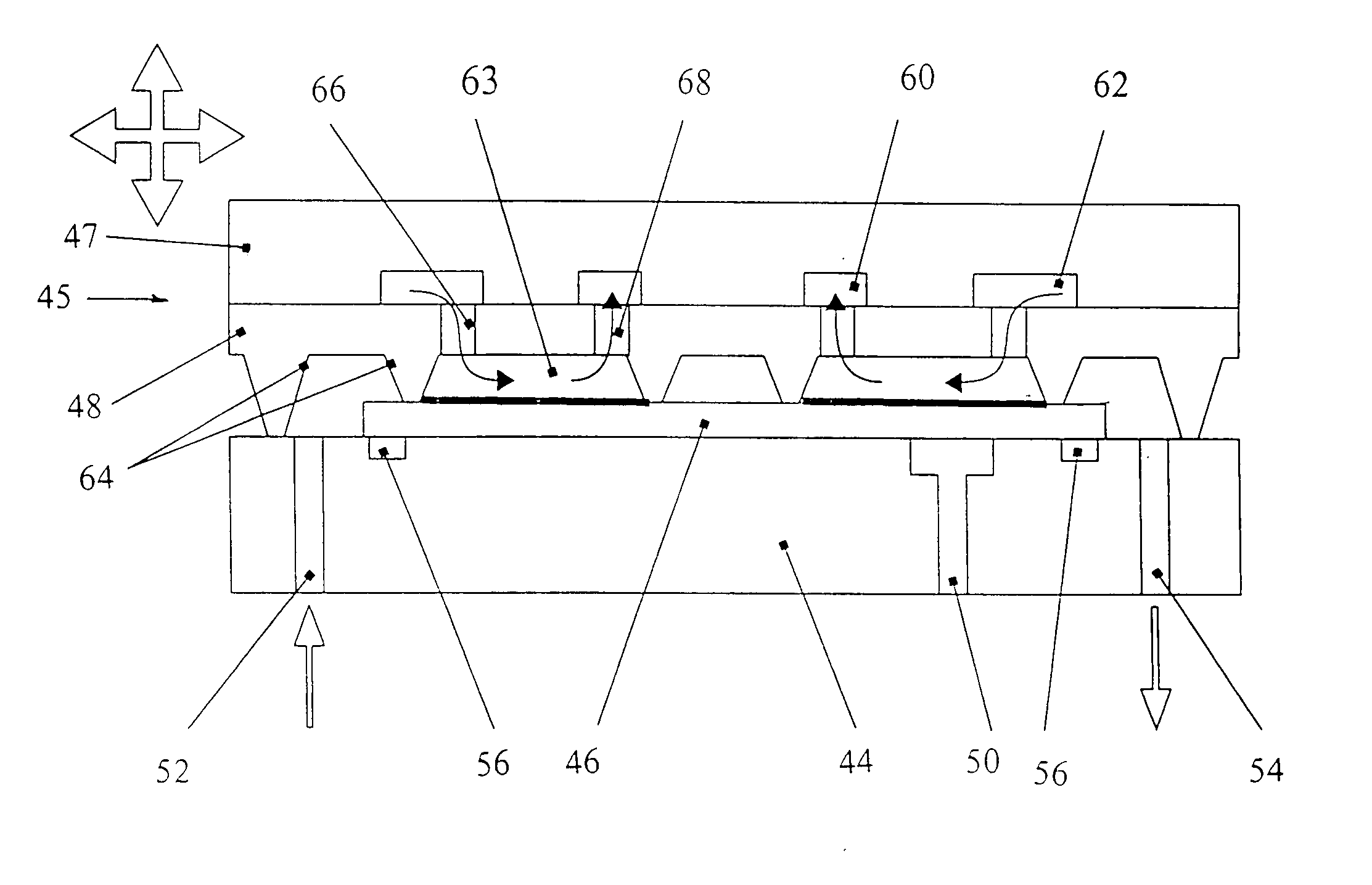
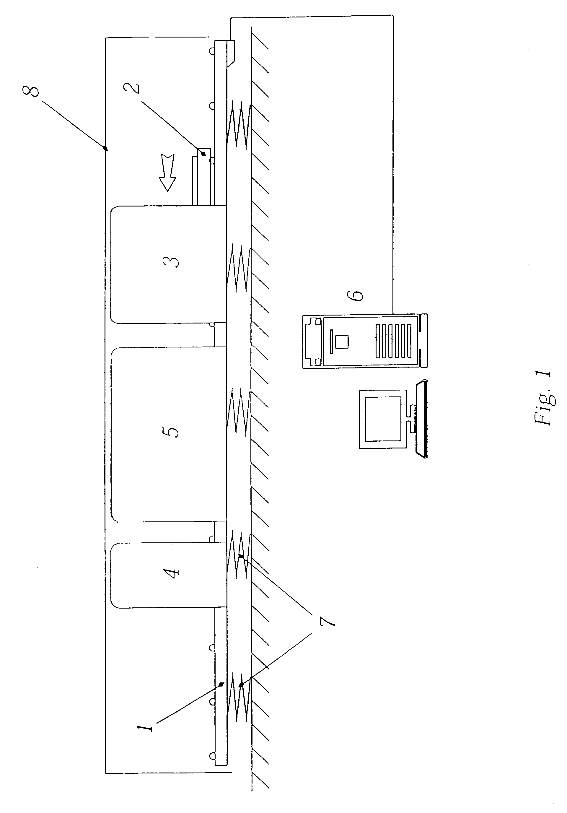
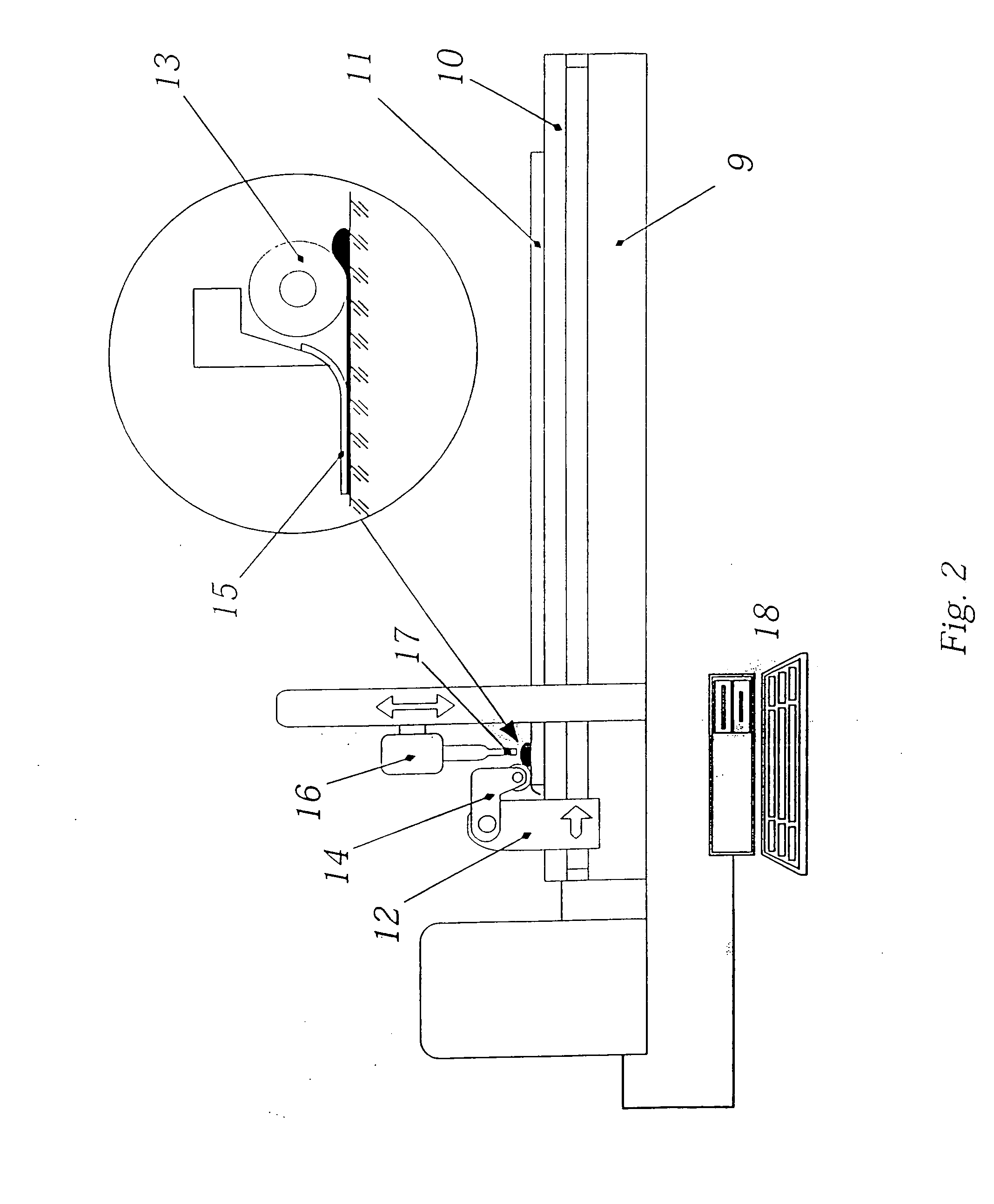
[0039] The major parts of the apparatus for application of polarizing coating (FIG. 1) are: the stand 1 (the base), on which all the working systems are situated, table 2 (substrate holder) for substrate placement, the system of polarizing film formation 3, the system of localized removal of the polarizing film material 4, the system of zonal drying 5, means of the relative mechanical movement of the table on the stand (not shown), the control block 6, anti-vibration system 7, the means to protect the working area from dust 8. Additionally to that, the apparatus can comprise a system of automatic supply onto the table and removal from it of the working substrates, the LLC and the working area temperature stabilizer, as well as any other systems and mechanisms providing automatic processing of substrates, enhancing the quality of polarizers or productivity of the apparatus. In FIG. 1, the system of zonal drying is situated between the system of formation and the system of local remov...


PUM

PropertyMeasurementUnit
thicknessaaaaaaaaaa
diameteraaaaaaaaaa
thicknessaaaaaaaaaa

Abstract

An apparatus for processing anisotropic films obtained from a liquid crystal solution containing at least one organic compound comprises means for holding a substrate carrying an anisotropic film and a processing facility including at least one channel or a system of connected channels, wherein the channel(s) is (are) provided with an input connected to means for supplying a working fluid and an output connected to a rarefaction or vacuum system, and at least a part of the channel(s) is open on the side of processed film. Means for moving the processing facility is provided to move the processing facility to the substrate. Means for pressing the processing facility to the surface of the anisotropic film and / or substrate is also provided.

Description

RELATED APPLICATIONS [0001] This application is divisional application of U.S. patent application Ser. No. 10 / 246,047 filed Sep. 17, 2002, which is a continuation-in-part of U.S. patent application Ser. No. 09 / 844,030 filed Apr. 26, 2001, which claims priority to Russian Application No. 2000117957 filed on Jul. 11, 2000, the disclosures of which are herein incorporated by reference.FIELD OF THE INVENTION [0002] The invention pertains to technological machinery for production of liquid crystal displays, in particular polarizers obtained from lyotropic liquid crystals based on organic compounds, particularly dyes. BACKGROUND OF THE INVENTION [0003] There is a known polarizer, obtained on the basis of liquid-crystal solutions of organic dyes as described in WO 94 / 28073. Polarizer, according to the herein technology, is obtained by application of thin film of liquid crystalline dye solution onto a glass or polymer substrate via one of the known methods. The distinction of this technolog...

Claims


Application Information

Patent Timeline
Patent Type & Authority Applications(United States)
IPC IPC(8): G02F1/1335G02B5/30
CPCB05C5/0212B05C5/025B05C11/1039G02B5/3016G02B5/3033
Inventor BOBROV, YURI A.
Owner NITTO DENKO CORP
Why Eureka
Try Eureka