Reflective and transflective liquid crystal display

a liquid crystal display and transflective technology, applied in non-linear optics, instruments, optics, etc., can solve the problems of limited view angle, limited view angle, and inability to compensate for all gray scale at all view angles

Inactive Publication Date: 2006-09-28
WINTEK CORP
View PDF7 Cites 9 Cited by
  • Summary
  • Abstract
  • Description
  • Claims
  • Application Information

AI Technical Summary

Benefits of technology

[0010] The secondary purpose of the present invention is to propose a semi-reflective structure, forming a wide view angle liquid crystal display with reflective effects which possesses advantages of both reflective and transmissive LCDs. The effect of wide view angle, excellent clarity of image both indoors and outdoors, and lower power consumption can be achieved.
[0011] The structure of the present invention includes a first substrate on which a pixel electrode is located. A bump structure is defined on the pixel electrode using a photolithography processes. Then a reflective layer is formed at the top or bottom of the peripheral of the bump structure under the pixel electrode to define the reflective zone and tansmissive zone. A polarizing layer covers the pixel electrode and the reflective layer. An upper electrode and a polarizer are installed on the surface of a secondary substrate. The transmissive axis of polarizer is normal to the polarizing layer. The upper electrode also contains a slit or a bump structure figure. Adjusting the relative position of the slit / bump structure between electrodes provides the liquid crystal molecules with pre-tilt angles and a controlled direction of tilt, forming a multi-domain division alignment. Meanwhile, the reflective zone and the transmissive zone form a semi-transmissive, semi-reflective liquid crystal display device as stated in the present invention. Hence the liquid crystal display device in the present invention will achieve the effect of wide view angle, excellent clarity of image both indoors and outdoors, and lower power consumption at the same time.

Problems solved by technology

The most frequently criticized about earlier liquid crystal display (LCD) is the limited view-angle.
Although a wider view angle can be obtained by attaching a high precision diffusion film, it is fixed after all, and is not capable of compensating for all gray scale at all view angles.
However, without optical compensation, the improvement of view angle is limited to the four directions (up, down, left and right) in MVA mode.
The strength of electric field is not uniform because of its special electrode arrangement.
Hence an incorrect grey scale display will occur if the strength of electric field is not high enough.
However, this requires additional power consumption.
However the upper-layer liquid crystal molecules which are further away from the electrodes will not gain the same momentum, hence the movement is slower.

Method used


Image

  • Reflective and transflective liquid crystal display
  • Reflective and transflective liquid crystal display
  • Reflective and transflective liquid crystal display

Examples


Embodiment Construction

[0035] The detailed contents and techniques of the present invention are described with figures as follows.

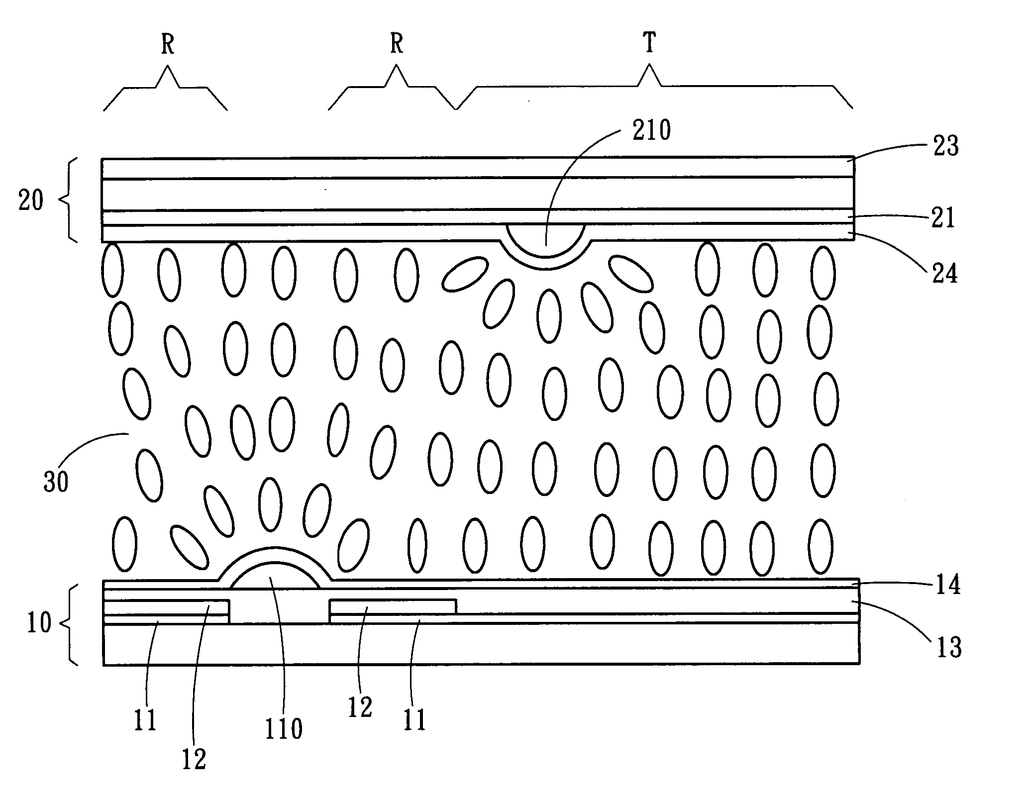
[0036] Referring to FIG. 6, the first schematic diagram of the structure of liquid crystal display in the present invention, the structure contains a first substrate 10 with a thin film transistor, and a pixel electrode 11 is installed on the top of the first substrate 10. Then a reflective layer 12 is deposited to cover part of pixel electrode 11 to define a reflective zone R, and a transmisive zone T of the pixel. The reflective layer 12 is made of low resistance and high reflectivity metallic materials (such as Al, Ag, Mo, Cr, AlNd etc.). A polarizing layer 13 is then formed to cover the reflective layer 12 and the pixel electrode 11. A pattern of bump structure 110 is then defined on the surface of polarizing layer 13 using a photolithography processes. The pattern of bump structure 110 within each pixel contains at least one dot-like bump. Also, the reflective layer 12 is...


PUM

PropertyMeasurementUnit
driving voltageaaaaaaaaaa
angleaaaaaaaaaa
resistanceaaaaaaaaaa

Abstract

A reflective and transflective liquid crystal display, a figure of bump structure is defined at a pixel electrode, and a reflective layer is formed around the peripheral at the top or bottom of the figure of bump structure to define the reflective zone and the transmissive zone of each single pixel. The upper electrode can contain the figure of slit or bump structure. By adjusting the relative positions of the figures of slit or bump structure between electrodes, the pre-tilt angles and tilting directions of liquid crystal molecules can be controlled, and a multi-domain division alignment is formed, and thus a multi-domain division, semi-transmissive, and wide view angle liquid crystal panel can be formed.

Description

FIELD OF THE INVETNION [0001] The present invention is about a semi-transmissive, semi-reflective, wide view angle liquid crystal display and its main feature includes the formation of multi-domain division and built-in reflective function. BACKGROUND OF THE INVENITON [0002] The most frequently criticized about earlier liquid crystal display (LCD) is the limited view-angle. Only within the range of ±45 degrees from the center of panel can present proper images. However the development and the increasingly diversified applications of large dimension panels, together with higher and higher demand for visual sensations, whether a liquid crystal display possesses the function of wide view angle is getting more and more important. [0003] There are presently two major wide view angle techniques: one is an external mode and the other is a built-in mode (For example Multi-domain Vertical Alignment, MVA, and In-Plane Switching, IPS, etc.). In U.S. Pat. No. 6,380,996, entitled “Optical Compen...

Claims


Application Information

Patent Timeline
Patent Type & Authority Applications(United States)
IPC IPC(8): G02F1/1335
CPCG02F1/133555G02F1/133707G02F1/133753
Inventor WANG, WEN-CHUNYU, MING-CHANGKANG, HENTA
Owner WINTEK CORP
Why Eureka
Try Eureka