Double-pass imaging pulse-stretcher

Inactive Publication Date: 2006-09-28
COHERENT INC
View PDF7 Cites 28 Cited by
  • Summary
  • Abstract
  • Description
  • Claims
  • Application Information

AI Technical Summary

Benefits of technology

[0011] The present invention is directed to apparatus for extending the duration and reducing peak power in an optical pulse. In one aspect apparatus in accordance with the present invention comprises an optical delay loop including a beamsplitter. The optical delay loop is in the form of an imaging optical system. The beamsplitter is arranged cooperative with the delay loop to divide the optical pulse into a first temporal sequence of pulse replicas each thereof having about the same beam dimensions, a first of which is transmitted by the beamsplitter and the remainder of which are reflected by the beamsplitter along the path of the transmitted replica. The sequence of pulse replicas propagates along a first common path. An optical arrangement is provided for directing the first sequence of pulse replicas back into the delay loop along a path laterally displaced from the first common path

Problems solved by technology

Indeed, in several such applications, too high a peak power can cause damage to whatever is being exposed to the radiation pulses, or to optical devices used to deliver the pulses.
This can become particularly problematical if a higher pulse-energy would be useful, while a maximum peak power must not be exceeded.
A high, peak pulse-intensity however can rapidly degrade optical elements of a projection system used

Method used


Image

  • Double-pass imaging pulse-stretcher
  • Double-pass imaging pulse-stretcher
  • Double-pass imaging pulse-stretcher

Examples


embodiment 30

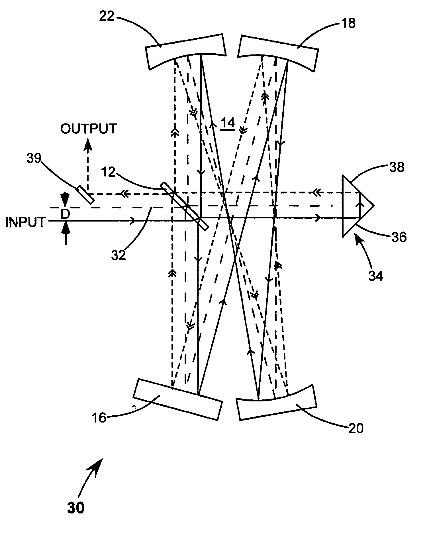
[0024] Referring now to the drawings, wherein like components are designated by like reference numerals, FIG. 4 schematically illustrates one preferred embodiment 30 of a double pass relay-imaging pulse-stretcher in accordance with the present invention. Pulse-stretcher 30, in this embodiment, includes a delay loop 14 with mirrors 16, 18, 20, and 22 arranged as described above in the pulse-stretcher of FIG. 1 to form a relay imaging optical system of about unit (about 1:1) magnification. The optical axis of the delay loop is depicted in FIG. 4 by a long dashed line 32.

[0025] Pulse-stretcher 30 makes use of the fact that the relay-imaging delay loop is insensitive to the position and pointing of an incident beam. After one round trip in the delay loop, the size, position, pointing, and divergence of the input beam are replicated, provided that the delay loop itself remains properly aligned. Tilting the delay loop or moving the delay loop (pulse-stretcher assembly), within certain lim...

embodiment 40

[0038]FIG. 10 schematically illustrates another preferred embodiment 40 of a double-pass, relay-imaging pulse-stretcher in accordance with the present invention. Pulse-stretcher 40 is similar to pulse-stretcher 30 of FIG. 4, with an exception that beamsplitter 12 of pulse-stretcher 30 is replaced in pulse-stretcher 40 by two different beamsplitters 12A and 12B on opposite sides of the optical axis of delay loop 14. These two beamsplitters, while depicted as being on separate substrates in FIG. 8, may simply be zones of different reflectivity on a common substrate. Beamsplitter 12A controls energy distribution in the once-stretched pulse, and beamsplitter 12B controls energy distribution in the twice stretched pulse.

[0039] Providing two separate beamsplitters means that one of the beamsplitters can have a different reflectivity from the other. For any given round trip loss value of the delay loop it is possible to find two different reflectivity values that will provide equal power i...


PUM


Abstract

A pulse-stretcher has an optical delay loop including a beamsplitter. The beamsplitter divides an input pulse into a temporal sequence of pulse replicas, a first of which is transmitted by the beamsplitter and the remainder of which are reflected by the beamsplitter along the path of the transmitted replica. The sequence of replicas form an initially stretched pulse having a longer duration and lower peak power than the input pulse. A prism cooperative with the delay loop reflects the initially stretched pulse back into the delay loop along a path laterally displaced from the replica path. The beamsplitter divides the initially stretched pulse into a temporal sequence of pulse replicas propagating along a common path to form a finally stretched pulse, having a longer duration and a lower peak power than the initially stretched pulse. The finally stretched pulse has a sequence of power peaks. Peak power in the pulse is minimized when the beamsplitter reflectivity is selected such that the power of the first two of these peaks is equal.

Description

TECHNICAL FIELD OF THE INVENTION [0001] The present invention relates to optical pulse-stretchers for reducing the peak power of laser pulses while conserving pulse energy. The application relates to such a pulse-stretcher in the form of an imaging delay line. DISCUSSION OF BACKGROUND ART [0002] In many applications where pulse laser radiation is used, for example, in laser material processing, laser printing, microlithography, and medical and surgical treatment, it is the energy of a pulse that is of interest rather than the peak power within the pulse. Indeed, in several such applications, too high a peak power can cause damage to whatever is being exposed to the radiation pulses, or to optical devices used to deliver the pulses. This can become particularly problematical if a higher pulse-energy would be useful, while a maximum peak power must not be exceeded. Since the duration of the laser pulse in most lasers is fixed, a pulsed laser providing higher energy would automatically...

Claims


Application Information

Patent Timeline
IPC IPC(8): H04B10/00
CPCH01S3/0057
Inventor WIESSNER, ALEXANDER O.SCHROEDER, THOMASALBRECHT, HANS-STEPHANAUSTIN, R. RUSSEL
Owner COHERENT INC
Why Eureka
Try Eureka