Mobile broadcast receiving apparatus and control method therefor

a mobile broadcasting and receiving apparatus technology, applied in the direction of broadcast system receiving, high-level techniques, broadcast with distribution, etc., can solve the problems of affecting the appropriate demodulation of waves, the relationship between the reception level between the gap filler wave and the satellite wave, and the inability to meet the needs of mobile broadcasting, etc., to achieve rapid recovery from image distortion, stable receiving of mobile broadcasting, and reducing power consumption

Inactive Publication Date: 2006-09-28
KK TOSHIBA
View PDF3 Cites 18 Cited by
  • Summary
  • Abstract
  • Description
  • Claims
  • Application Information

AI Technical Summary

Benefits of technology

[0037] According to the above-mentioned aspects of the invention, a mobile broadcast receiving apparatus, which selectively receives either a broadcast radio wave from a geostationary satellite or a radio wave retransmitted from a gap filler, is designed to control switching of at least one of a dynamic range of a low noise amplifier (LNA), a time constant of an automatic gain control circuit (AGC), and ON and OFF of antenna diversity, according to a reception status of the mobile broadcast receiving apparatus. Therefore, the mobile broadcast receiving apparatus is capable of stably receiving mobile broadcasting even if rapid variation occurs in the level of received waves. The mobile broadcast receiving apparatus is also capable of rapidly recovering from image distortion and reducing power consumption.

Problems solved by technology

However, the possibility is low that the relationship in reception level between the gap filler waves and the satellite waves is reversed.
This may eventually hinder appropriate demodulation of the waves.
In the region 2 where the reception level of the gap filler waves on average is substantially equal to the reception level of the satellite waves, for example, rapid switching between the gap filler waves and the satellite waves may become impossible due to the time constant of the automatic gain control circuit (AGC).
This will pose a problem of wasteful consumption of power.

Method used


Image

  • Mobile broadcast receiving apparatus and control method therefor
  • Mobile broadcast receiving apparatus and control method therefor
  • Mobile broadcast receiving apparatus and control method therefor

Examples


first embodiment

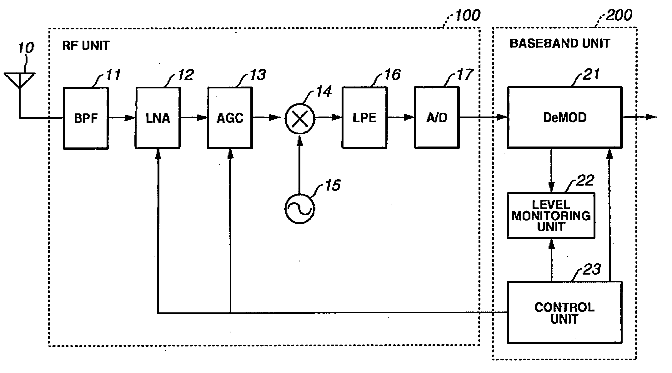
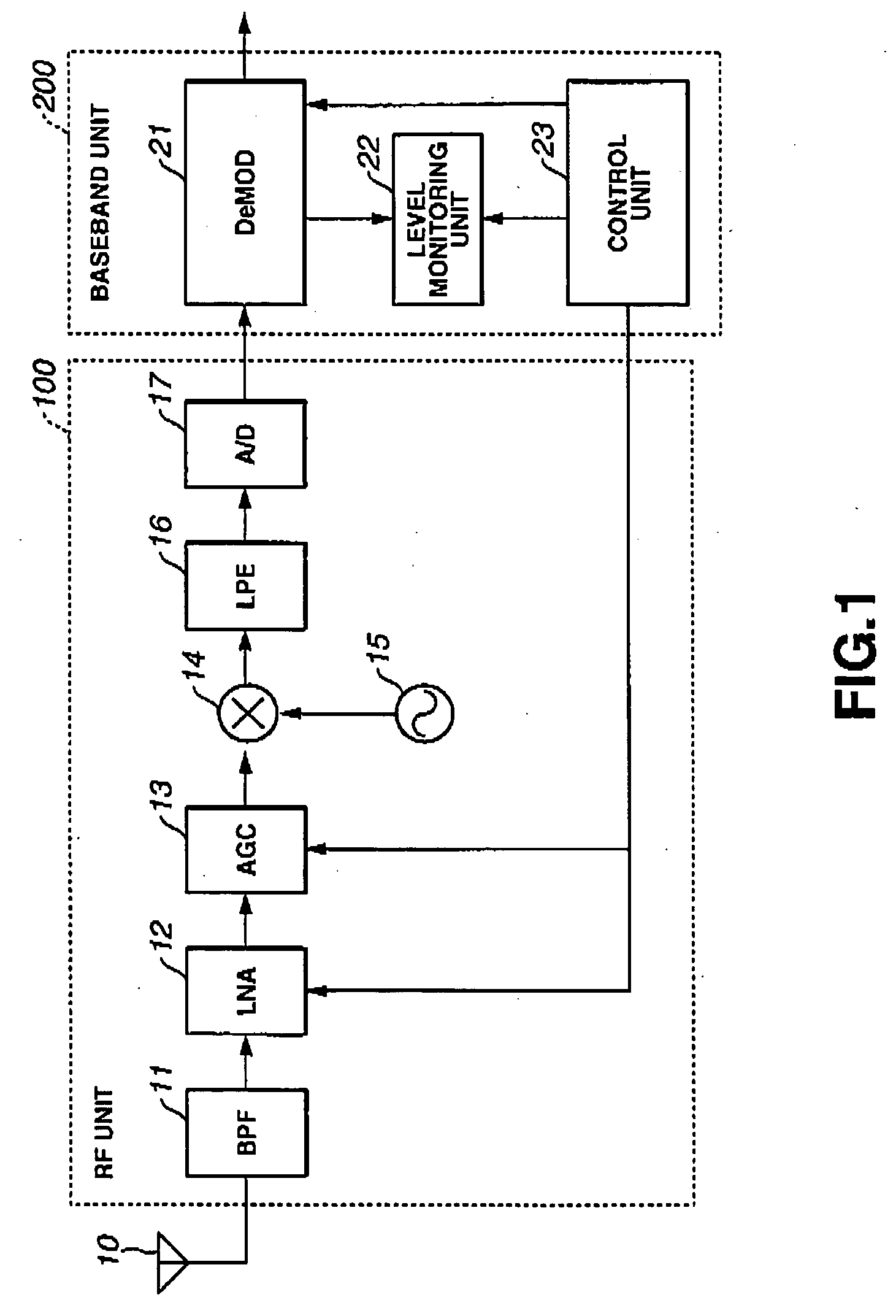
[0058] According to a first embodiment, the control unit 23 in the configuration shown in FIG. 1 controls the switching of dynamic range of the LNA 11 according to the reception level of received waves and information indicating whether the waves being received are satellite waves or gap filler waves.

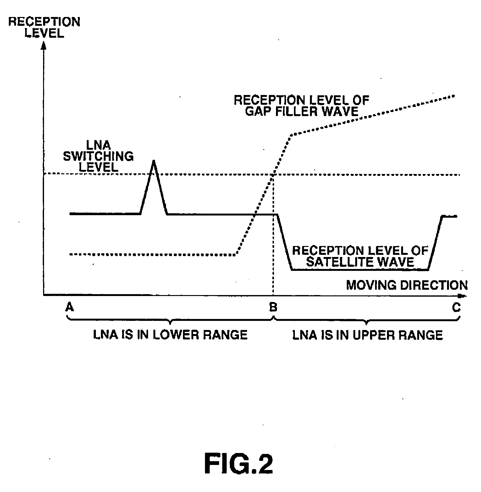
[0059]FIG. 2 illustrates the switching control of the dynamic range of the LNA 11 according to the first embodiment.

[0060]FIG. 2 shows, like FIG. 10, the reception level of the mobile broadcast receiving apparatus and the switching status of the dynamic range of the LNA 11 when a user carrying the mobile broadcast receiving apparatus moves in the field with the distributed electric field strength shown in FIG. 9 from point A, to point B, and to point C.

[0061] In the first embodiment, the dynamic range of the LNA 11 is fixed to a lower range when the received waves are satellite waves or when the reception level of the gap filler waves is relatively low, that is, while the user carryi...

second embodiment

[0079] According to a second embodiment, the control unit 23 in the configuration shown in FIG. 1 controls the switching of the time constant of the AGC 13, according to a switching frequency between the reception of satellite waves and the reception of gap filler waves.

[0080] The switching control of the time constant of the AGC 13 can be performed by feedback control of the reception level from the control unit 23.

[0081]FIG. 4 illustrates the switching control of the time constant of the AGC 13 according to the second embodiment.

[0082] As shown in FIG. 10, when the user carrying the mobile broadcast receiving apparatus moves in the field with the distributed electric field strength shown in FIG. 9 from point A, to point B, and to point C, the reception level of the mobile broadcast receiving apparatus of the gap filler waves is on average lower than the reception level of satellite waves in the region R1 where the user moves from point A to point B. In the region R3 where the u...

third embodiment

[0101] According to configuration of a third embodiment of this invention, an antenna diversity function is employed to make it possible to receive satellite waves from a geostationary satellite and gap filler waves from a gap filler in a still more stable manner.

[0102]FIG. 6 is a block diagram showing a principal part of a mobile broadcast receiving apparatus employing an antenna diversity function according to the third embodiment of this invention.

[0103] Referring to FIG. 6, the antenna diversity function is realized by providing an RF unit 100 for processing a radio signal received by an antenna 10 and an RF unit 300 for processing a radio signal received by an antenna 30, and switching between the output of the RF unit 100 and the output of the RF unit 300 by the control unit 23.

[0104] Specifically, as shown in FIG. 6, the RF unit 100 includes, like the RF unit 100 shown in FIG. 1, a bandpass filter (BPF) 11 which band-pass filters a radio signal received by the antenna 10, ...


PUM


Abstract

A mobile broadcast receiving apparatus capable of stably receiving mobile broadcasting even with rapid variation in a reception level and yet capable of reducing the power consumption and a control method for such apparatus are provided. The mobile broadcast receiving apparatus, which selectively receives a broadcast radio wave from a geostationary satellite or a radio wave retransmitted from a gap filler, controls switching of at least one of a dynamic range of a low noise amplifier (LNA), a time constant of an automatic gain control circuit (AGC), and ON / OFF of an antenna diversity, according to a reception status of the mobile broadcast receiving apparatus.

Description

CROSS-REFERENCE TO RELATED APPLICATIONS [0001] This application is based upon and claims the benefit of priority from the prior Japanese Patent Application No. 2005-91530, filed on Mar. 28, 2005; the entire contents of which are incorporated herein by reference. BACKGROUND OF THE INVENTION [0002] 1. Field of the Invention [0003] This invention relates to a mobile broadcast receiving apparatus which selectively receives either broadcast radio waves from a geostationary satellite or radio waves retransmitted from a gap filler according to reception levels thereof, and a control method for such apparatus. In particular, this invention relates to a mobile broadcast receiving apparatus which is capable of rapid recovery from image distortion and reducing the power consumption by appropriately controlling the switching of the dynamic range of a low noise amplifier (LNA), the time constant of an automatic gain control circuit (AGC), and ON and OFF of antenna diversity, and a control method...

Claims


Application Information

Patent Timeline
Patent Type & Authority Applications(United States)
IPC IPC(8): H04H1/00H04B1/16H04B7/08H04B7/155H04B7/19
CPCH04H20/02H04H40/27H04H40/90Y02D30/70H04B7/216H04N7/20
Inventor TAKANO, KOJI
Owner KK TOSHIBA
Why Eureka
Try Eureka