Robot controller and robot control method

Active Publication Date: 2006-09-28
KAWASAKI HEAVY IND LTD
View PDF7 Cites 52 Cited by
  • Summary
  • Abstract
  • Description
  • Claims
  • Application Information

AI Technical Summary

Benefits of technology

[0045] As mentioned above, according to the present invention, the standard moving parts of the robots can be prevented from stopping during movement from the movement start positions to the synchronous operation positions. Therefore, even if the moving speed and movement distance are varied between the robots, there is no need to keep each standard moving part waiting at the synchronous operation position. Therefore, the moving speed of each robot can be prevented from increasing unnecessarily, and the energy consumption can be reduced, and the energy efficiency can be improved. Further, the standard moving parts can be moved smoothly.
[0046] Furthermore, the operator does not need to adjust the moving speed and movement distance of each robot so as to simultaneously move the standard moving part of each robot to each synchronous operation position. Further, the operator, even if the mo

Problems solved by technology

However, if the first robot 1 is excessively slowed down, even if the workpiece 9 after pressing reaches the separation position p3, a condition that the workpiece 8 before pressing does not reach yet the proximity position p1 is caused and a problem arises that the cycle time is increased.
Further, the timing adjustment by hand must be made whenever changing the

Method used


Image

  • Robot controller and robot control method
  • Robot controller and robot control method
  • Robot controller and robot control method

Examples


Embodiment Construction

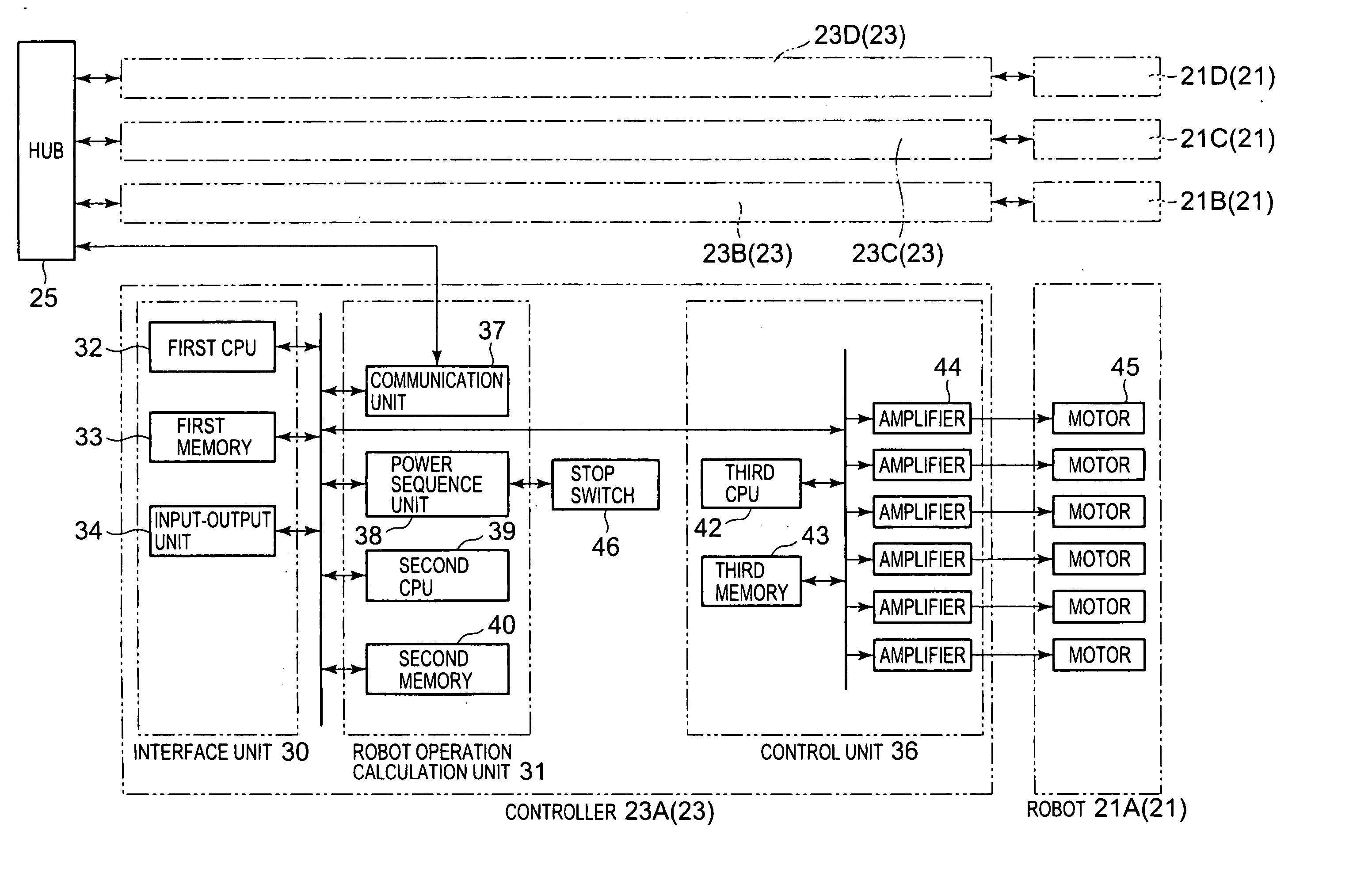
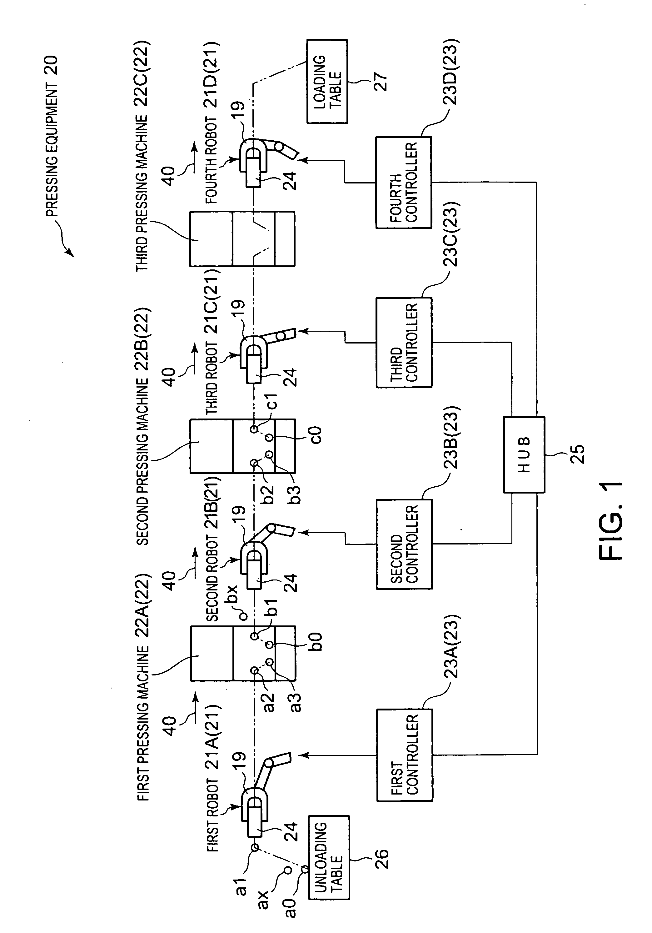
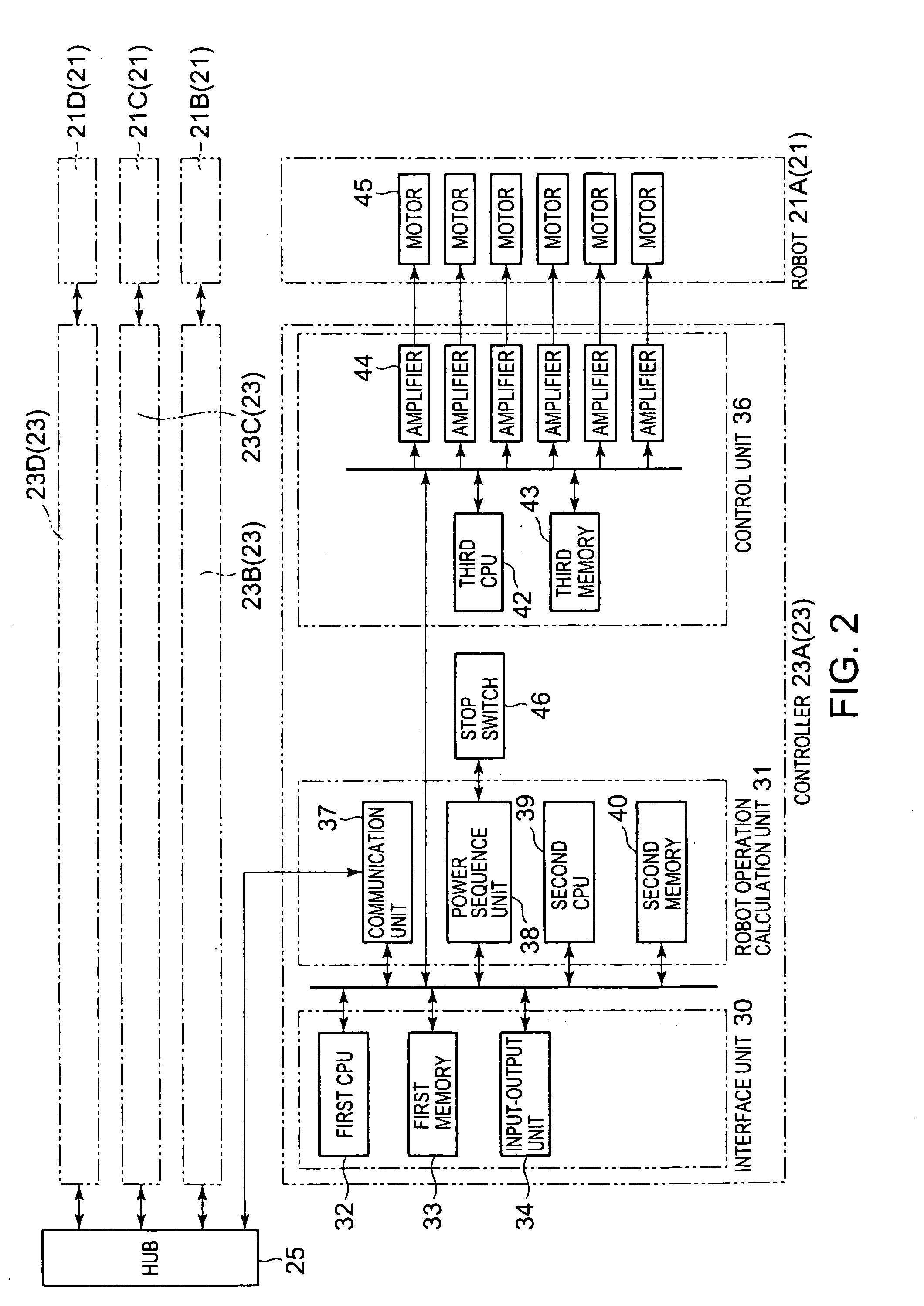
[0072] Referring to FIG. 1, the pressing equipment 20 is structured so as to include a plurality of pressing machines 22, a plurality of robots 21 for transferring a workpiece 24 between the pressing machines 22, a plurality of robot controllers 23 for controlling respectively the robots 21, and a hub 25 composing a communicating means for communicably connecting the robot controllers 23. In this embodiment, the pressing equipment 20 is equipped with three pressing machines 22A to 22C and four robots 21A to 21D.

[0073] Each robot 21 is a multi-axial robot and in this embodiment, is realized by a six-axial vertical multi-joint robot. The robot 21 is equipped with a rotational body on a base installed on the floor. On the rotational body, a plurality of arms are installed so as to change the angle around each axis. At the front end of the arm at the freest end, a wrist is installed. On the wrist, the robot hand 19 removably holding the workpiece 24 is installed. The robot hand 19 is a...


PUM


Abstract

A controller calculates first movement times when moving each robot hand from a movement start position to a synchronous operation position in a shortest time and decides the longest first movement time as a second movement time. The controller generates, for each robot, a robot operation plan for moving each robot hand without stopping from the movement start position to the synchronous operation position in the second movement time. The robot hand of each robot moves from the movement start position to the synchronous operation position without stopping and simultaneously reach the synchronous operation positions.

Description


Claims


Application Information

Patent Timeline
Owner KAWASAKI HEAVY IND LTD
Why Eureka
Try Eureka