
Control system and communication system for digital mixer

a control system and communication system technology, applied in the direction of electric digital data processing, broadcast information generation, instruments, etc., can solve the problems of increasing production costs, unavoidably increasing the number of devices on the isup>2/sup>c bus, and the bus interface is more complicated than the serial communication interface, so as to reduce production costs, prevent data collision, and simplify the configuration

Inactive Publication Date: 2006-09-28
YAMAHA CORP
View PDF5 Cites 18 Cited by
  • Summary
  • Abstract
  • Description
  • Claims
  • Application Information

AI Technical Summary

Benefits of technology

[0007] The present invention has been made in view of the above problems, and it is an object of the present invention to provide a control system and a communication system for reducing the number of devices connected to a complicated serial bus (e.g., I2C bus), and at the same time implementing communication between several devices.
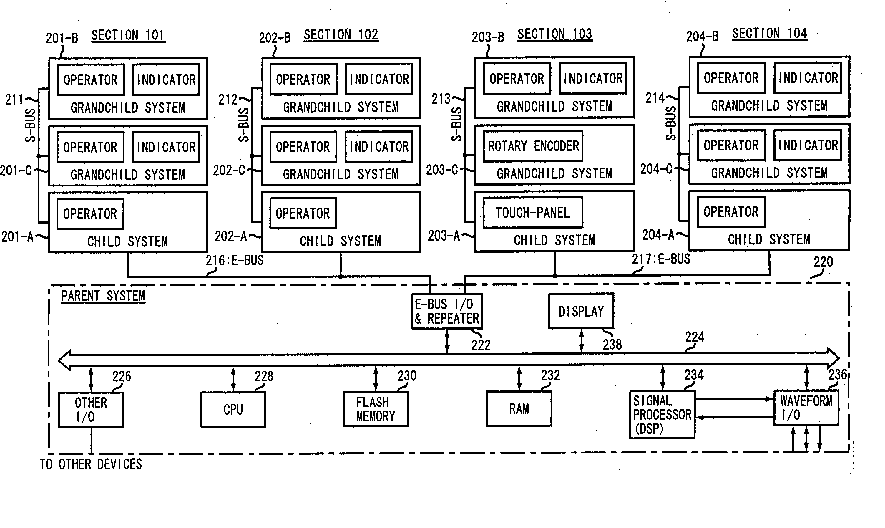
[0019] In this manner, according to the inventive control system in which each of the first class devices is connected via the first class bus, and each second class device is connected to the first class device via the second class bus, the number of the first class devices, which require a specific function for adding source and destination addresses to data, can be reduced by the number of the second class devices. Moreover, the second class device which does not require the specific function for adding source and destination addresses to data input / output operations is cheaper than the first class device, resulting in the implementation of simplified configuration and reduced production costs.
[0020] In this way, according to the communication system of the present invention, the status information transmitter contained in the master device transmits status information including a communication direction flag, one of the master data transmitter and the slave data transmitter transmits data, and data communication begins after a device that must transmit data is determined by the master device. For example, the present invention prevents data collision which would be caused by simultaneous data transmission by a plurality of devices, resulting in increased reliability of data communication. In addition, there is no need to perform an arbitration process when data collision occurs, resulting in reduction of system costs.
[0021] Further according to the present invention, each slave device can verify the error check code irrespective of whether each slave device is designated as a communication party, such that the slave device directly unconcerned with data communication is able to serve as a check device, and resources of the slave device are effectively used, resulting in increased system reliability.
[0022] Moreover according to the present invention, each slave device outputs a transmission request signal to the master device via the third connection line, such that it can quickly inform the master device of the transmission request without generating a communication failure between the master device and other slave devices than the above-mentioned slave device.

Problems solved by technology

Therefore, the number of repeaters for use in an apparatus composed of a plurality of devices is also increased, resulting in increased costs of production.
Specifically, the digital mixer includes more numbers of operators and indicators. than those of the electronic musical instruments, such that it has a disadvantage in that it must unavoidably increase the number of devices on the I2C bus.
For example, the bus interface is more complicated than a serial communication interface such as an RS232C.

Method used


Image

  • Control system and communication system for digital mixer
  • Control system and communication system for digital mixer
  • Control system and communication system for digital mixer

Examples


Embodiment Construction

1. Hardware Configuration of Embodiment

1.1 Operation Panel (100) Configuration

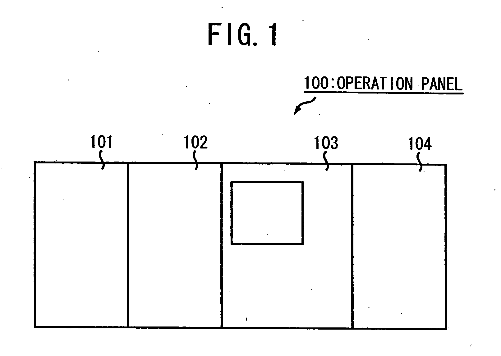
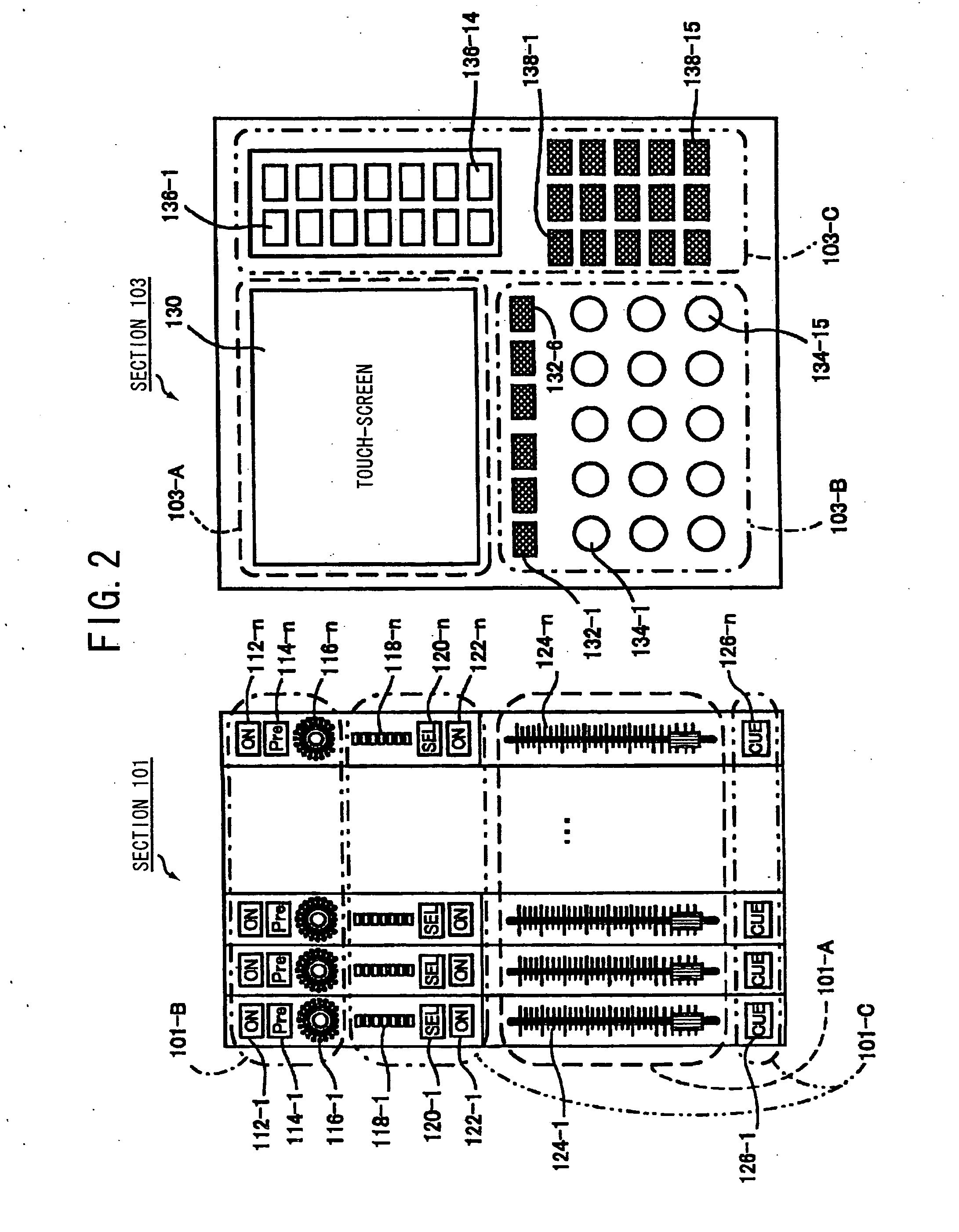
[0040] The operation panel (100) for use in the digital mixer according to a preferred embodiment of the present invention will hereinafter be described with reference to FIG. 1. The operation panel 100 is composed of four sectors (i.e., sections 101˜104). Each of the sections 101 and 102 includes a fader (or the like) for adjusting the volume of an input channel. Likewise, the section 104 includes a fader (or the like) for adjusting the volume of an output channel. The section 103 is adapted to establish detailed parameters for use in a single channel selected from among I / O channels. An audio signal equipped with adjusted volume- and sound quality-levels in individual input channels is outputted to a plurality of buses (i.e., a stereo bus, a MIX bus, and a CUE bus, etc.).

[0041] In this case, the stereo bus is indicative of a bus for mixing an audio signal capable of absorbing sound at guest seats. T...


PUM


Abstract

In a control system of a digital mixer, first class devices are connected via a first class bus, and second class devices are connected to each first class device via a second class bus. The number of first class devices, which require a specific function for adding source and destination addresses to data, can be reduced by the number of the second class devices. Moreover, the second class device which does not require the specific function for adding source and destination addresses to data input / output operations is cheaper than the first class device, resulting in the implementation of simplified configuration and reduced production costs.

Description

BACKGROUND OF THE INVENTION [0001] 1. Technical Field of the Invention [0002] The present invention relates to a control system and a communication system capable of being properly used to control a digital mixer or the like. [0003] 2. Description of the Related Art [0004] Conventionally, a serial bus (i.e., an I2C bus) for enabling a plurality of devices to communicate with each other via two signal lines has been well known to those skilled in the art. A specific bus (i.e., an E-bus) formed by applying the I2C bus to data communication between internal devices (e.g., a keyboard, a panel operator, an indicator, and a sound source, etc.) contained in an electronic musical instrument has been disclosed in Japanese Patent Laid-open Publication No. 2002-251183 and corresponding U.S. Pat. No. 6,700,050. A plurality of addresses from 1 to 127 are assigned to individual devices for use in the I2C bus, respectively. Therefore, a maximum of 127 devices can be theoretically connected to the ...

Claims


Application Information

Patent Timeline
Patent Type & Authority Applications(United States)
IPC IPC(8): G06F13/38
CPCG06F13/4291H04H60/04
Inventor HOTTA, HARUMICHIKUDO, MASAKIAISO, MASARU
Owner YAMAHA CORP
Learn More