Dynamically interleaving randomly generated test-cases for functional verification

a random generation and functional verification technology, applied in the direction of testing circuits, instruments, program control, etc., can solve the problems of time-consuming and laborious development of test templates, and achieve the effect of large investmen

Inactive Publication Date: 2006-09-28
GLOBALFOUNDRIES INC
View PDF34 Cites 31 Cited by
  • Summary
  • Abstract
  • Description
  • Claims
  • Application Information

AI Technical Summary

Benefits of technology

[0012] It may be noted that the development of test templates is often a time consuming process, which requires a large investment of human effort. It is an advantage of some aspects of the i...

Problems solved by technology

It may be noted that the development of test templates is often a t...

Method used


Image

  • Dynamically interleaving randomly generated test-cases for functional verification
  • Dynamically interleaving randomly generated test-cases for functional verification
  • Dynamically interleaving randomly generated test-cases for functional verification

Examples


example 1

[0041] For example, consider a multi-processor system with an I / O subsystem—it would be desirable to have a test case that targets cache operations for the processors, and at the same time tests direct memory accesses (DMA) coming from an I / O device.

example 2

[0042] In another example, assume that a computer employing a single processor has been previously verified through the construction of test templates, each directed to particular functions of the design-under-verification. Now a multiprocessor version is to be verified, in which software can selectively disable or enable one or more processors as a function of computational load. It is now necessary to test the processor enable / disable functions in combination with all the other functions of the single processor version. As will be seen from the discussion that follows, according to some aspects of the invention, test templates, which were originally constructed for the single processor version, can be reused and combined with a new template that is directed to the processor enable / disable functions. The old and new templates are interleaved so as to test complex scenarios involving different numbers of operating processors.

[0043] Yet another common requirement is to interleave hi...

example 3

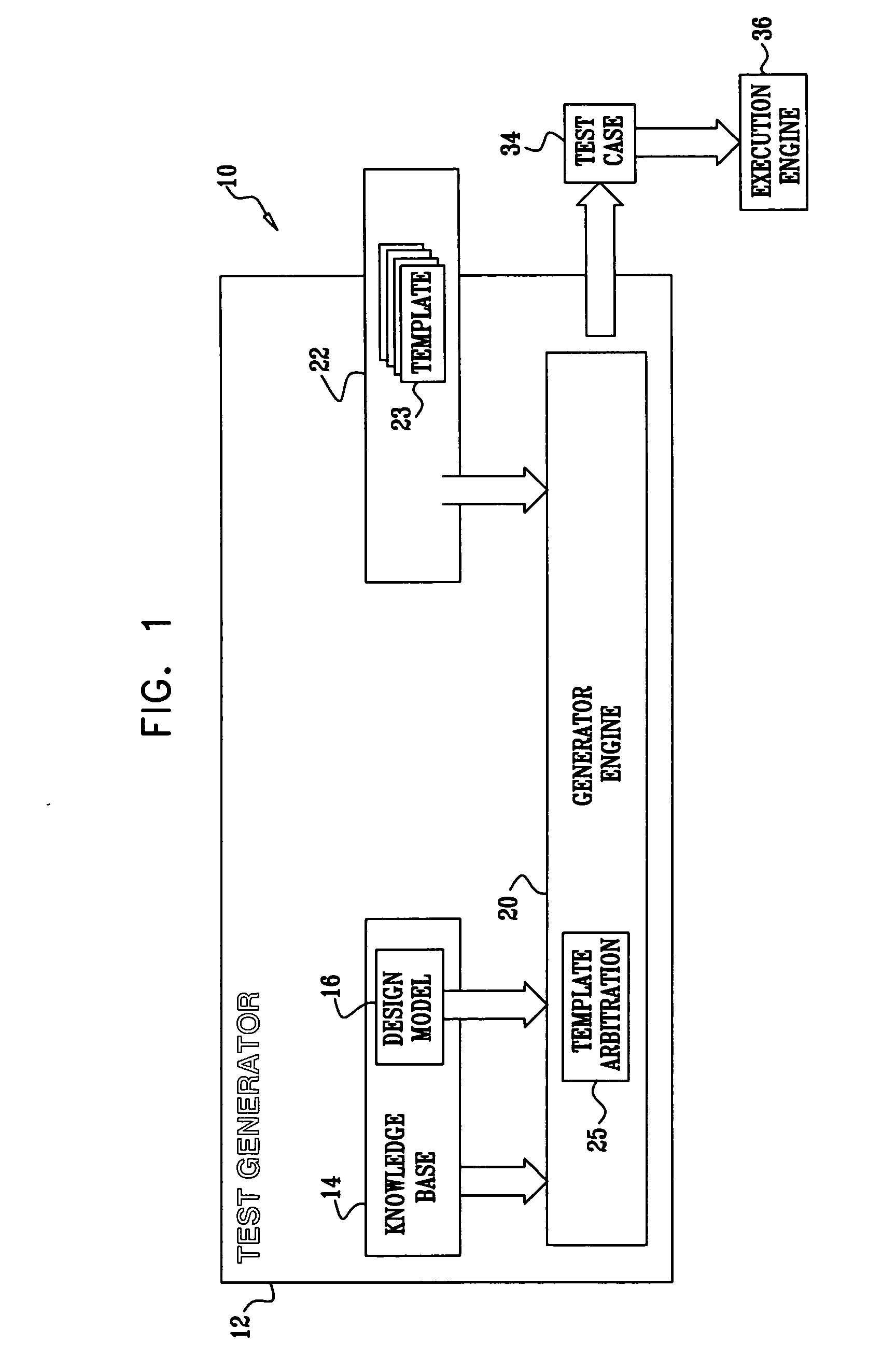
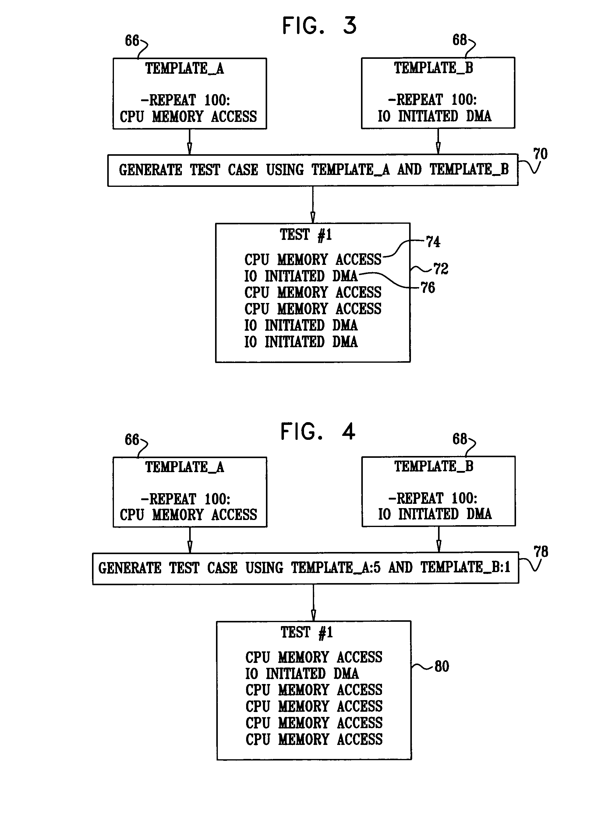
[0073] Reference is now made to FIG. 3, which is a diagram illustrating a simple example of interleaving test templates to produce a test case for a design-under-verification in accordance with a disclosed embodiment of the invention. In this example, there are two templates 66, 68. The template 66 specifies that the test generator 12 (FIG. 1) is to generate instructions that perform 100 CPU-initiated memory accesses. The template 68 specifies the generation of instructions that result in 100 I / O initiated direct memory accesses (DMA). In block 70, representing a random test generator, the templates 66, 68 are interleaved in a random manner that is nevertheless consistent with any constraints imposed by the model 16.

[0074] Alternatively, a relative weight for each of the templates 66, 68 can be assigned. The test generator 12 then generates transactions according to the assigned weight ratios. In general, in order to comply with the assigned weights, transactions corresponding to o...


PUM


Abstract

The input for a test generator is a plurality of test templates, each of which typically aims at covering a specific verification task. Test templates direct the production of distinct transactions, which are the atomic functional building blocks of the design-under-verification. Test templates directed to different hardware functions of the scenario are dynamically interleaved. In this way several transactions are combined together in complex statements in order to achieve a complex test scenario. The transactions are submitted to the test generator, which generates test cases, in which the different hardware functions of the scenario are exercised in combinations. Variation among the test cases is achieved through a large number of random decisions made during the generation process.

Description

BACKGROUND OF THE INVENTION [0001] 1. Field of the Invention [0002] This invention relates to functional verification of a design. More particularly, this invention relates to systems and methods for the efficient creation of test cases in order to verify combinations of several different functions of a hardware or software design. [0003] 2. Description of the Related Art [0004] Functional verification is widely acknowledged to be a bottleneck in a hardware system's design cycle. Indeed, up to 70% of development time and resources are typically spent on functional verification. Allowing users to find design flaws, and fixing them in a subsequent release would be unwise and costly for three main reasons: (1) harm to reputation and brand-name; (2) a high cost of recall and replacement when there is a large installed base; and (3) litigation, should design flaws cause injury. [0005] In current industrial practice, dynamic verification is the main functional verification technique for l...

Claims


Application Information

Patent Timeline
IPC IPC(8): G06F17/50G06F9/45
CPCG01R31/318371G06F17/5022G06F30/33
Inventor DOZORETS, IGOREMEK, ROYGUPTA, SANJAYJAEGER, ITAIMCCONVILLE, LAWRENCE ALLYNSCHECHNER, TZACHSWANSON, TODD
Owner GLOBALFOUNDRIES INC
Why Eureka
Try Eureka