Shaving implement having a moving blade

a technology of shaving implements and blades, which is applied in the field of shaving implements, can solve the problems of unpleasant pulling on hair, adverse effects of reducing the tip diameter of razor blades, and the efforts to date have not been entirely successful, and achieve the effect of significantly reducing the cutting force required to shave, when the blades are moving in the blade plan

Inactive Publication Date: 2006-10-05
EVEREADY BATTERY CO INC
View PDF11 Cites 59 Cited by
  • Summary
  • Abstract
  • Description
  • Claims
  • Application Information

AI Technical Summary

Benefits of technology

[0013] One advantage of the present invention is that the when the blade(s) move in the blade plane, the blade(s) tend to chop the hair. Accordingly, the cut force required to shave, when the blades are moving in the blade plane, is significantly redu

Problems solved by technology

Efforts to date have not been entirely successful, typically due to the difficulties posed by the “cut force” of the razors during shaving.
Friction between a hair and the razor blade is often the source of unpleasant pulling on the hair during shaving.
However, reducing the tip diameter of

Method used


Image

  • Shaving implement having a moving blade
  • Shaving implement having a moving blade
  • Shaving implement having a moving blade

Examples


embodiment 1

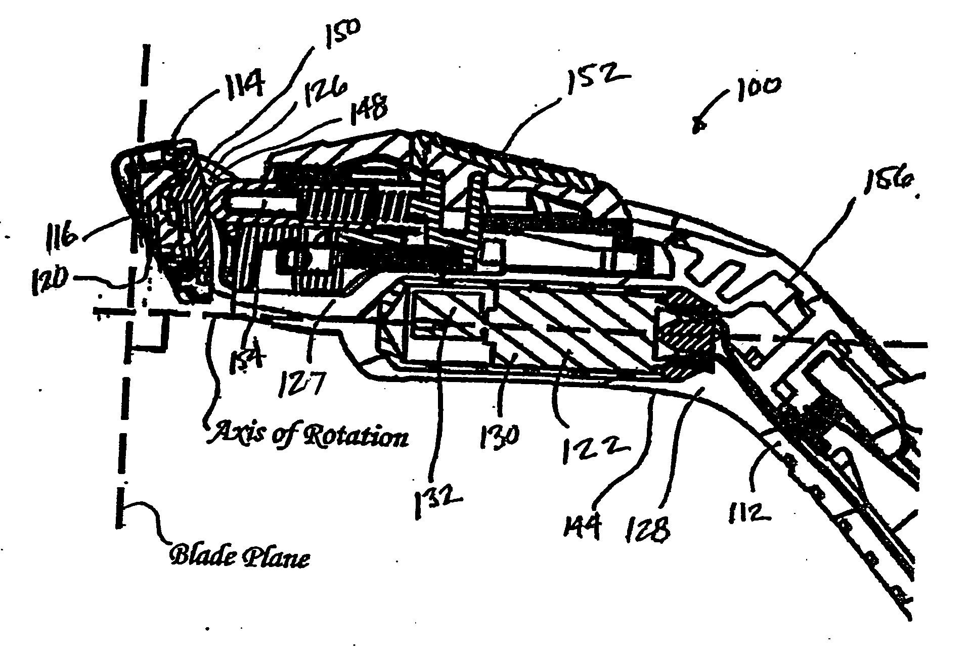
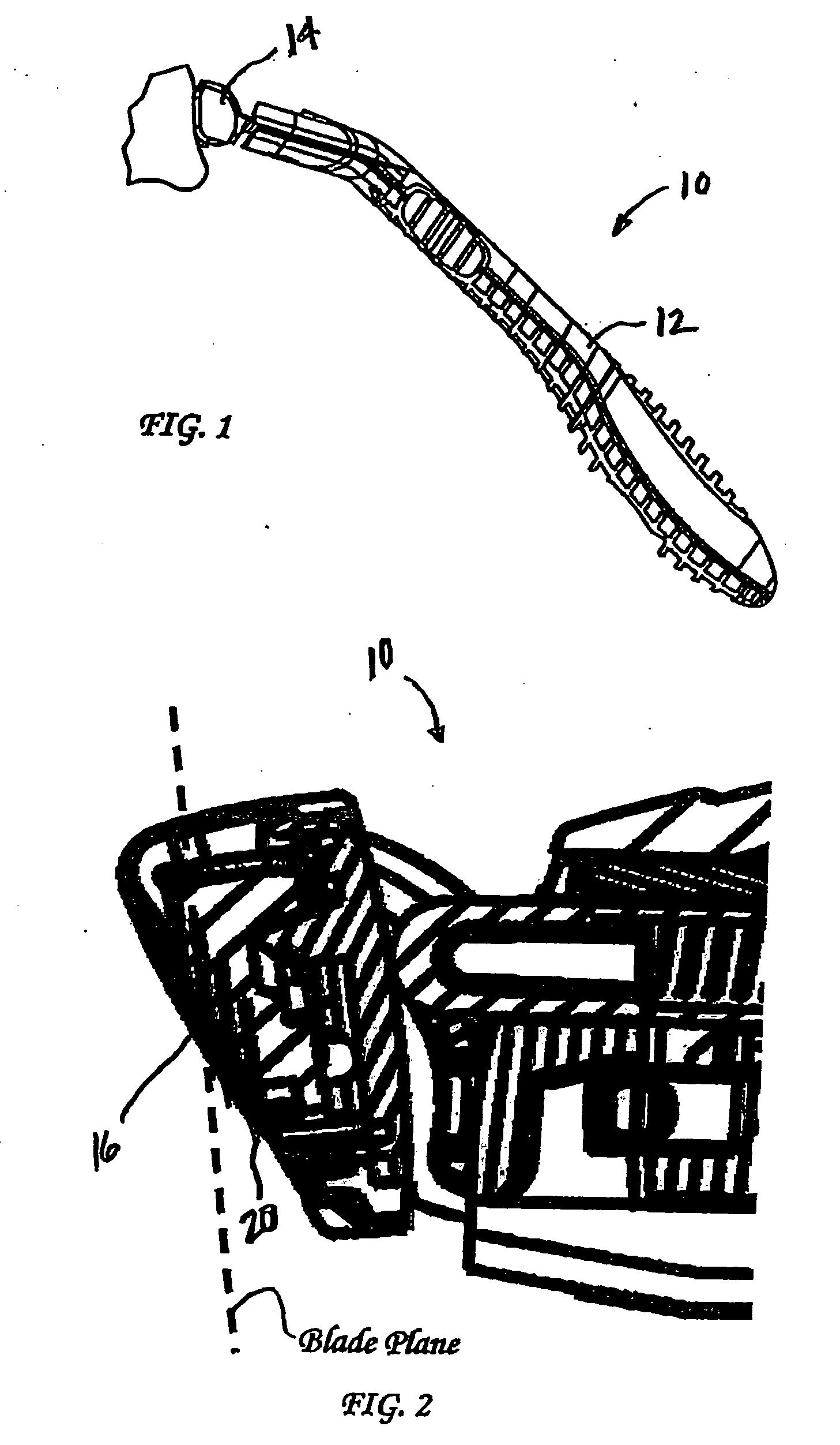
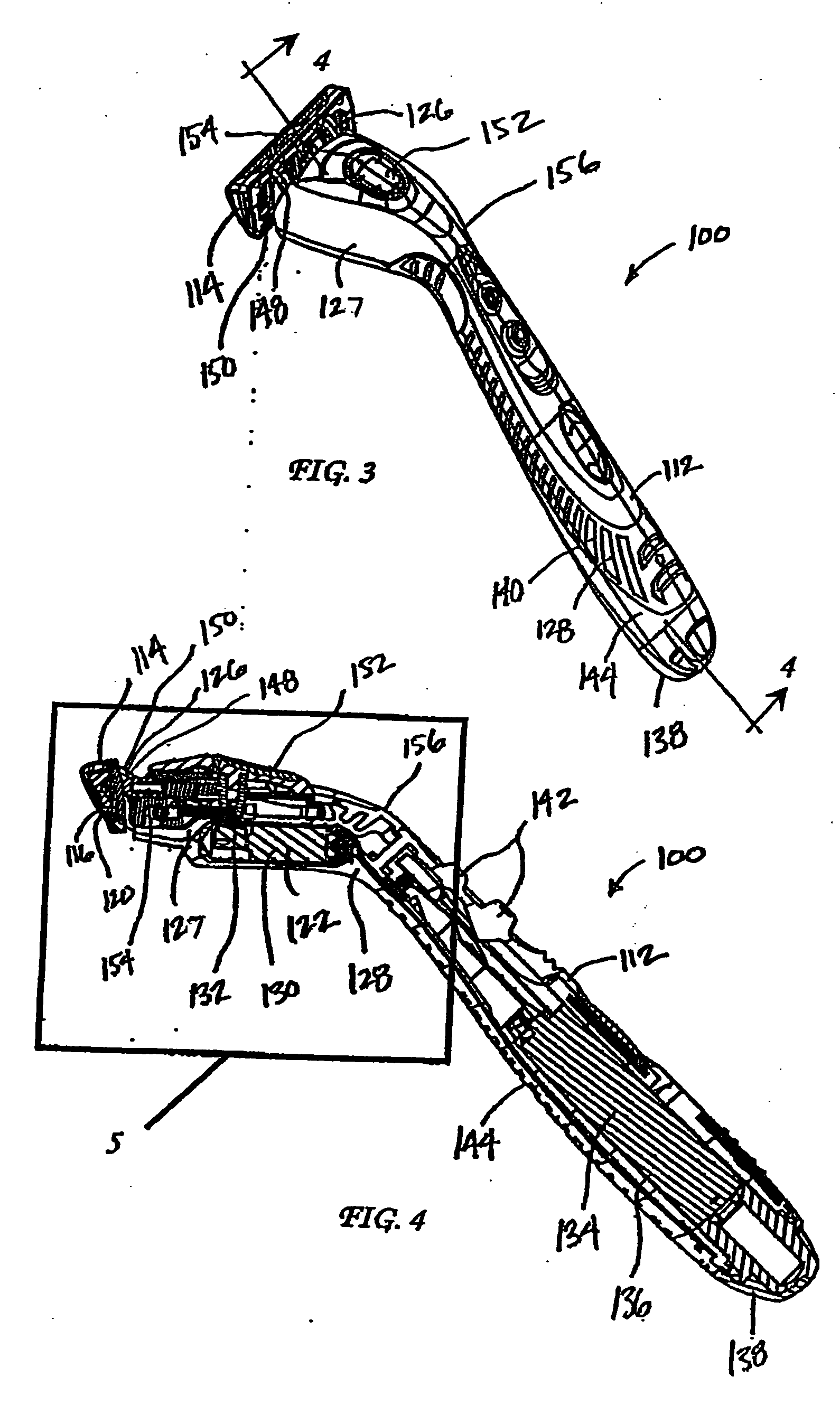
[0026] Referring to FIGS. 3-4, the shaving implement 100 includes a handle 112, and a razor cartridge 114. The razor cartridge 114 includes at least one blade 116 having a sharpened cutting edge 120, and defines a blade plane. The handle 112 includes a vibration mechanism 122, and a cartridge-connecting member 126.

[0027] Although the handle 112 of the shaving implement 110 of the present invention can be made in numerous manners, using numerous types of materials, the following manner has shown particular utility. The handle 112, in some embodiments such as the ones shown in FIGS. 4 and 5, can include a first molded portion 127, a vibration mechanism 122, and a second molded portion 128. The first molded portion 122 can be formed of a rigid molded material that provides the razor handle 112 with the necessary mechanical strength. For example, the first molded portion 127 may be made of Glass Fiber Polypropylene (“GFPP”), which has proven to have desirable density (1.00 g / cm3), tens...

embodiment 2

[0037] In a second embodiment of the present invention, and now referring to FIGS. 6-9, the shaving implement 200 includes a handle 212. In the second embodiment, the mechanism 18 is a dithering mechanism 224. In these embodiments, the cartridge 214 comprises a housing 226 defining an interior chamber 228 in which the razor blade 216 and the dithering mechanism 214 are mounted. As is known, the cartridge 214 can be pivotally connected to the handle 212, as discussed above with respect to the first embodiment. As shown more particularly in FIGS. 7 and 8, the housing 226 includes a back section 230, a top section 232, and generally opposed side sections 234. While the housing 226 is shown as having separably defined sections, the above-defined sections may be integrally formed (e.g., during a molding operation). The general shape of the housing 226 preferably sets the angle of the blade(s) 216 and, more particularly, the cutting edge 220 against the skin surface, as shown, for example...


PUM


Abstract

The present invention is related to a shaving implement that includes at least a razor cartridge and a mechanism. The razor cartridge includes at least one blade that has a sharpened cutting edge and defines a blade plane. The mechanism is disposed in the shaving plane and moves the blade in the blade plane during shaving. The mechanism may be either a vibration mechanism (i.e., a motorized spinning eccentric weight), or a dithering mechanism (i.e., a piezoelectric element). The cut force required to shave, when the blades are moving in the blade plane, is significantly reduced.

Description

CROSS REFERENCE TO RELATED APPLICATIONS [0001] This application is entitled to the benefit of and incorporates by reference the disclosure of U.S. Patent Application 60 / 668,761 filed on Apr. 5, 2005, entitled “Shaving Implement Having a Moving Blade.”BACKGROUND OF THE INVENTION [0002] 1. Field of the Invention [0003] The present invention relates generally to shaving implements, and more particularly, to shaving implements having at least one moving blade. [0004] 2. Description of the Prior Art [0005] In general, shaving implements, also commonly referred to as wet-shave devices, attempt to simultaneously satisfy three important functional areas: comfort, closeness, and safety. Over the years, new technologies have been utilized in shaving implement designs to improve closeness and safety, and, in general, make such shaving implements more efficient at their intended task. Efforts to date have not been entirely successful, typically due to the difficulties posed by the “cut force” o...

Claims


Application Information

Patent Timeline
IPC IPC(8): B26B21/52B26B19/28
CPCB26B21/526B26B21/38
Inventor NOBLE, DAVIDPENNELLA, ANDREW J.
Owner EVEREADY BATTERY CO INC
Why Eureka
Try Eureka