Cylinder liner

Inactive Publication Date: 2006-10-05
IPD CORP
View PDF4 Cites 16 Cited by
  • Summary
  • Abstract
  • Description
  • Claims
  • Application Information

AI Technical Summary

Benefits of technology

[0007] The present invention is directed to a cylinder liner having a curved cross-section circulation cooling groove located neighboring the top flange for the cylinder liner, thus to extend the effective volume of the cooling chamber higher on the cylinder liner in respect to the combustion zone. This improves the heat transfer between the cylinder liner and the surrounding coolant at this critical locati

Problems solved by technology

The cylinder liners now sold for use with these types of engines are typically made of chilled cast iron with a thorough hardness on the range of 45-

Method used


Image

  • Cylinder liner
  • Cylinder liner
  • Cylinder liner

Examples


Embodiment Construction

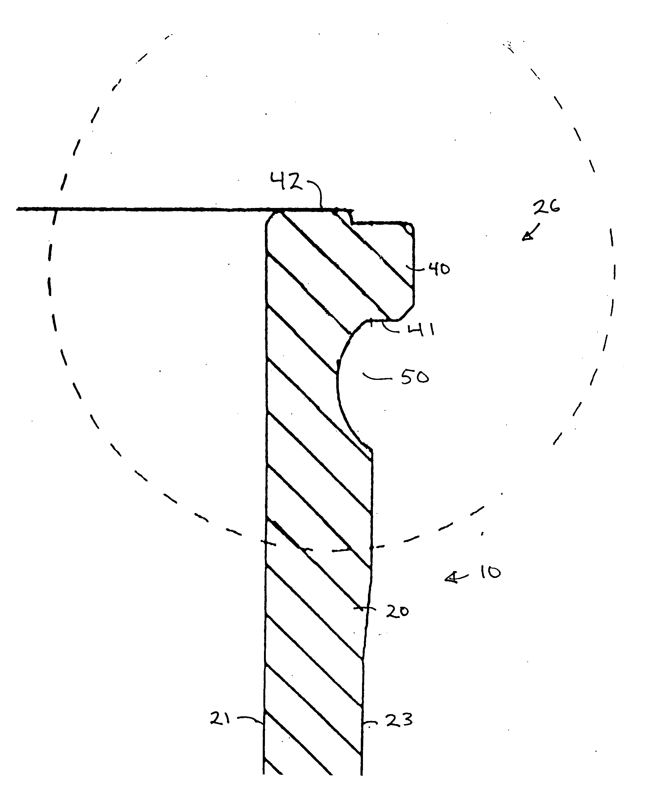
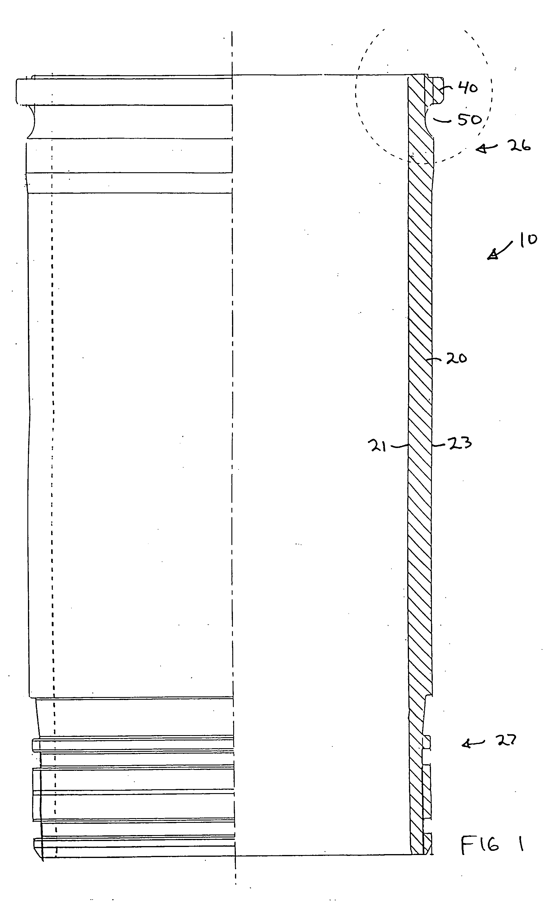
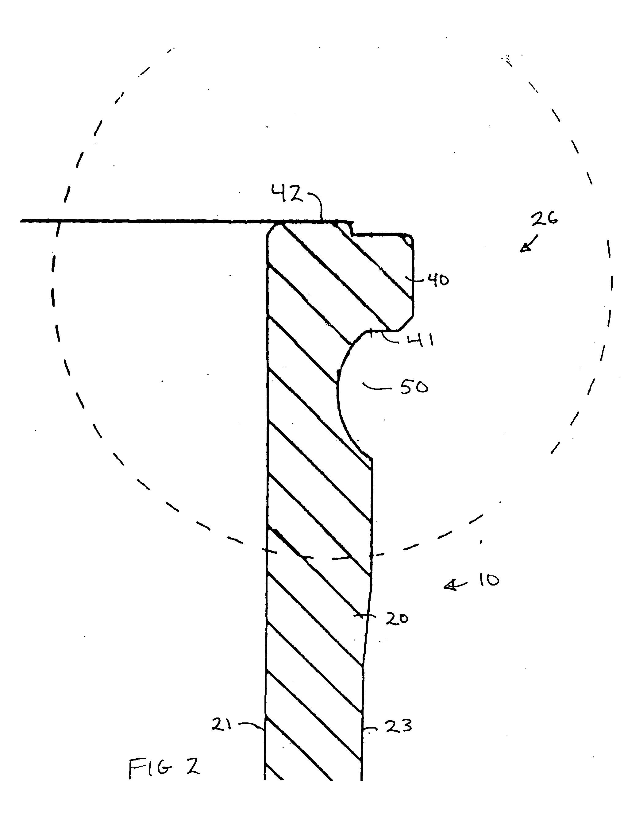
[0021] This invention relates to an improved cylinder liner for use in internal combustion engines. An example would be to utilize the liner in an after-market repair of a Detroit diesel 60 or 70 series engine.

[0022] The cylinder liner 10 itself includes a wall 20 extending off of a radially extending flange 40.

[0023] The cylinder liner 10 is designed to be pressed into a cylinder block 11 in a-known manner. The cylinder liner 10 thereafter cooperates with the cylinder head 12 and the piston 13 so as to create the combustion chamber for the engine. In the diesel engine shown, the engine uses direct injection with the combustion chamber 14 being supplemented by a swirl chamber in the piston (preferred) or head in order to optimize the apparent combustion chamber of the engine while simultaneously providing for a physical clearance for an injector and an auxiliary start glow plug that may be incorporated into high compression diesel engines. This allows a minimum clearance between t...


PUM

PropertyMeasurementUnit
Angleaaaaaaaaaa
Pressureaaaaaaaaaa
Diameteraaaaaaaaaa

Abstract

A ductile repair cylinder liner for a diesel engine, the cylinder liner having an additional cooling groove with a parabolic varying cross-section machined into the outer surface of the cylinder liner immediately below the radially extending locating flange for the liner.

Description

FIELD TO WHICH THE INVENTION RELATES [0001] This invention relates to a coolant circulation groove in a cylinder liner for the passage of cooling liquids in internal combustion engines together with the method of manufacture thereof. BACKGROUND OF THE INVENTION [0002] Internal combustion engines are efficient ways of creating power in movable and fixed applications. Examples of the former include vehicles such as trucks, tractors and boats. Examples of the latter include generators, pumps, welders and the like. [0003] A substantial after-market has developed for repair and rebuilding of these engines, with normal wear on removable parts like liners, piston rings, and bearings. These parts have to be periodically replaced in order to maintain the service life of individual engines. [0004] With newly formulated low emission fuels, increasing compression ratios, boost pressures, operating temperatures, exhaust gas recirculation, speeds and other parameters, an efficient way of providin...

Claims


Application Information

Patent Timeline
IPC IPC(8): F02F1/10
CPCY10T29/49293F02F1/004
Inventor RASMUSSEN, ROBERT
Owner IPD CORP
Why Eureka
Try Eureka