
Control device for a diesel engine

Inactive Publication Date: 2006-10-05
MITSUBISHI FUSO TRUCK AND BUS CORPORATION
View PDF3 Cites 33 Cited by
  • Summary
  • Abstract
  • Description
  • Claims
  • Application Information

AI Technical Summary

Benefits of technology

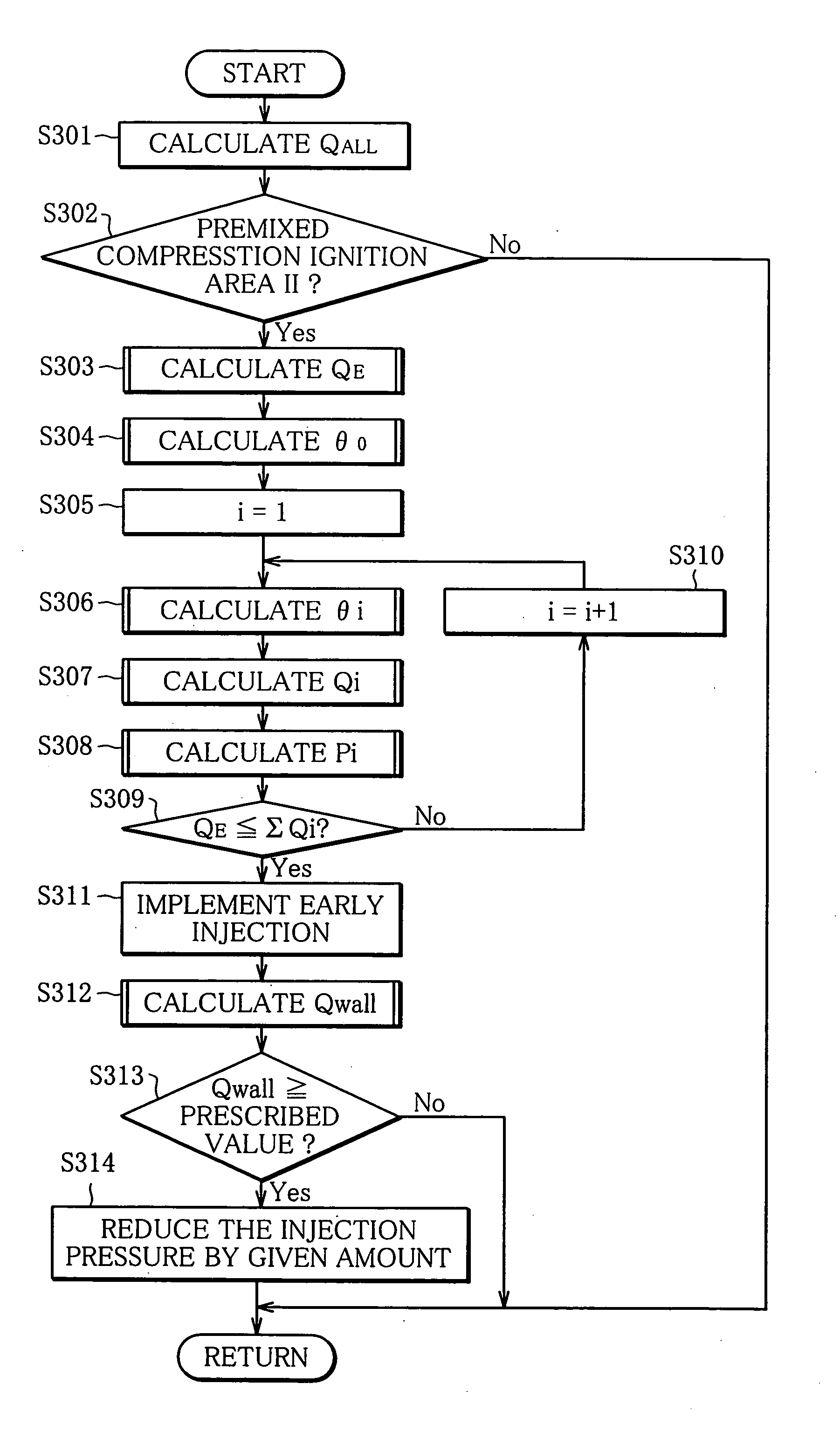
[0012] By so doing, the injection pressures of the respective stages are not set to equal pressures but to pressures that vary depending on the respective injections. Furthermore, since the injection pressures of the respective stages are adjusted according to the gas density and the gas temperature in the cylinder, the fuel spray penetration that suits the actual conditions is taken into account. As a consequence, the injection of each stage can be set at a highest suitable pressure in a range where fuel spray does not adhere to a wall surface of the cylinder. This makes it possible to achieve suppression of oil dilution, smoke reduction, and an improvement in combustion efficiency.

Problems solved by technology

In the process of the HCCI combustion, when the injection quantity grows as the demanded load is increased, the fuel is pre-ignited, and combustion is intensified, which causes knocking.
There also arouses the fear that a large quantity of NOx and smoke might be produced.
The fuel injected with the early timing in the compression stroke, however, reaches as far as a cylinder wall surface, which triggers oil dilution and smoke.
Unless the injection pressure is changed according to the state in the cylinder at the time of injection, it is impossible to actually prevent the fuel from reaching the cylinder wall surface.
This causes the problem that especially the fuel injected at the first stage is liable to reach the cylinder wall surface.
Such evaluation is hard to apply in case that all fuel is combusted in the inside of cylinders.
However, without consideration of atmosphere temperature (gas temperature) in the cylinder in addition to the gas density, the fuel spray penetration does not follow actual conditions, and the quantity of the fuel that actually adheres to the cylinder wall surface cannot be evaluated.
Another reason is that a rise in the intake temperature reduces the gas density but increases the gas temperature, so that the fuel spray penetration in this case is on the decline due to fuel evaporation, which decreases the possibility that the fuel reaches the cylinder wall surface.

Method used


Image

  • Control device for a diesel engine
  • Control device for a diesel engine
  • Control device for a diesel engine

Examples


Embodiment Construction

[0025] An embodiment of the present invention will be described below with reference to the drawings.

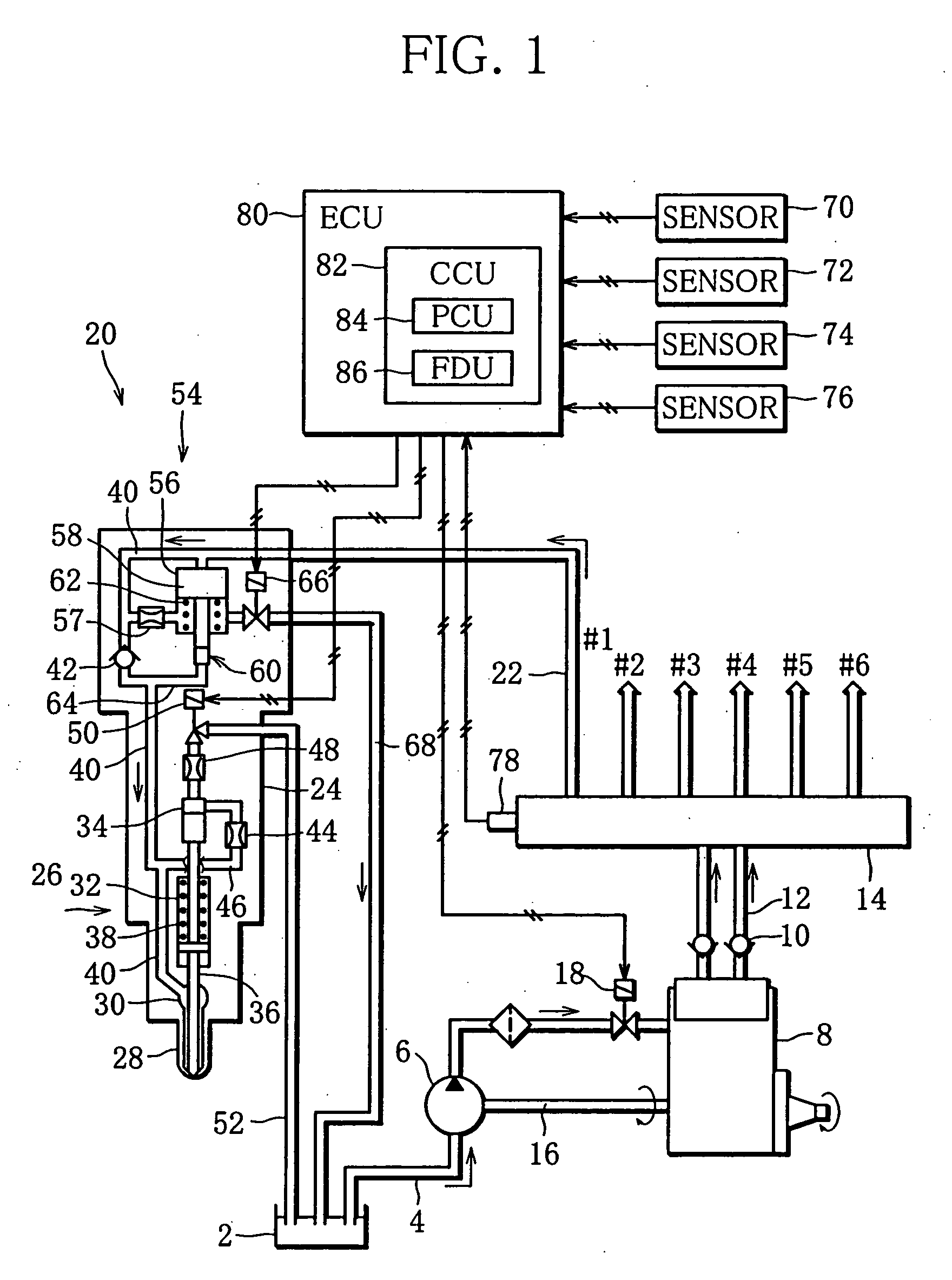
[0026]FIG. 1 is a view showing an entire constitution of a fuel injector with a common rail. A control device for a diesel engine according to the present invention is applied to the injector.

[0027] A vehicle equipped with the diesel engine (hereinafter simply referred to as engine) includes a fuel tank 2. The tank 2 is connected to a feed pump 6 through a fuel passage 4. The pump 6 is connected to a supply pump 8. The pump 8 is provided with an electromagnetic adjusting valve 18 and connected to a common rail 14 through a pair of fuel passages 12 with respective check valves 10. The pumps 6 and 8 are formed integrally and activated by engine through a drive shaft 16.

[0028] Fuel contained in the tank 2 is pumped up by the pump 6 and supplied to the pump 8. The fuel is then pressurized in the pump 8 and supplied to the common rail 14. Suction amount of the fuel supplied to the pump...


PUM


Abstract

There are provided a diesel engine that injects fuel into air compressed in cylinders and combusts the fuel by spontaneous ignition, and a control unit that sets the fuel injection timing to an earlier time point than the compression top dead center to premix air and fuel and combusts the air-fuel mixture compressed in the cylinders by spontaneous ignition. The control unit injects the fuel to be injected in an early stage in a plurality of stages according to the operation state of the engine and individually adjusts the injection pressures of their respective stages according to the gas density and the gas temperature in the corresponding cylinder.

Description

BACKGROUND OF THE INVENTION [0001] 1. Field of the Invention [0002] The present invention relates to a control device for a diesel engine, which advances a fuel injection timing to be earlier than in diesel combustion, and carries out the Premixed Compression Ignition that injects fuel in a plurality of stages. [0003] 2. Description of the Related Art [0004] Generally in the diesel combustion (diffusion combustion), air is taken into cylinders to be compressed. Fuel is then injected into the compressed air to be combusted by spontaneous ignition. Aside from this method, there is another combustion method, namely Homogeneous Charge Compression Ignition (HCCI) combustion, which advances the fuel injection timing considerably to elongate an ignition delay period. This method produces a lean mixture and combusts the mixture at low temperature, thereby suppressing the generation of NOx and smoke. [0005] In the process of the HCCI combustion, when the injection quantity grows as the deman...

Claims


Application Information

Patent Timeline
IPC IPC(8): F02D41/40
CPCF02D35/025F02D41/047F02D41/3035Y02T10/44F02D41/401F02D41/402F02D41/3836Y02T10/40F02D41/40F02D41/04
Inventor OKUDE, KEIICHISHIINO, SHIROHMORIYA, TAKESHI
Owner MITSUBISHI FUSO TRUCK AND BUS CORPORATION
Learn More