Ultraviolet radiation water treatment system

a radiation water treatment system and ultraviolet light technology, applied in the direction of machines/engines, process and machine control, sedimentation settling tanks, etc., can solve the problems of water system contamination accidents, abnormal odor and taste, aggregation and deposition inhibition, and other problems, to achieve the effect of generating harmful by-products, and reducing the number of radiation radiation sources

Active Publication Date: 2006-10-05
KK TOSHIBA
View PDF14 Cites 25 Cited by
  • Summary
  • Abstract
  • Description
  • Claims
  • Application Information

AI Technical Summary

Problems solved by technology

However, in recent years, there have occurred water system contamination accidents caused by emerging or reemerging pathogenic microbes such as cryptosporidium, giargia and the like.
Further, the mass generation of algae through eutrophication of lakes, dams, and rivers as water system water sources, and increasing pollution by organic matters and the like has caused abnormal odor and taste, coloring disorders, aggregation and deposition inhibition, filtration blockage, leakage into filtered water, and other problems.
Furthermore, there has occurred a problem where chlorine agents to be injected into water for sterilization react with organic matters in raw water, thereby generating harmful by-products such as trihalomethanes (It is the general term showing the total amount of Chloroform, Bromoform, Bromodichloromethane, and Dichlorochloromethane.).
These problems have come t

Method used


Image

  • Ultraviolet radiation water treatment system
  • Ultraviolet radiation water treatment system
  • Ultraviolet radiation water treatment system

Examples


first embodiment

(Operation and Effects of First Embodiment)

[0053] Hereinafter, the operation and effects of the present embodiment will be explained.

[0054] The controller 14 calculates the respective ultraviolet illuminances in the insides of the front stage ultraviolet radiation device 5 and the rear stage ultraviolet radiation device 10 by use of the following equation (1). Herein, the ultraviolet illuminance is maximum at the surface of the ultraviolet lamp, and decreases gradually away from the lamp. The decrease amount at this moment is calculated with an ultraviolet transmittance to a fluid to be treated (raw water or sedimented water) flowing in the piping, and a distance from the lamp surface: I=(UV4⁢ ⁢π⁢ ⁢Z02)⨯exp⁡(ln⁡(T / 100)⨯Z)⁢⁢(mW / cm2)(1)

where I means an ultraviolet illuminance (mW / cm2); Uv means an ultraviolet output of the lamp (mW); T means an ultraviolet transmittance (%), Z0 means a distance from the lamp (cm); and Z means a distance in which ultraviolet penetrates the raw water...

second embodiment

(Operation and Effects of Second Embodiment)

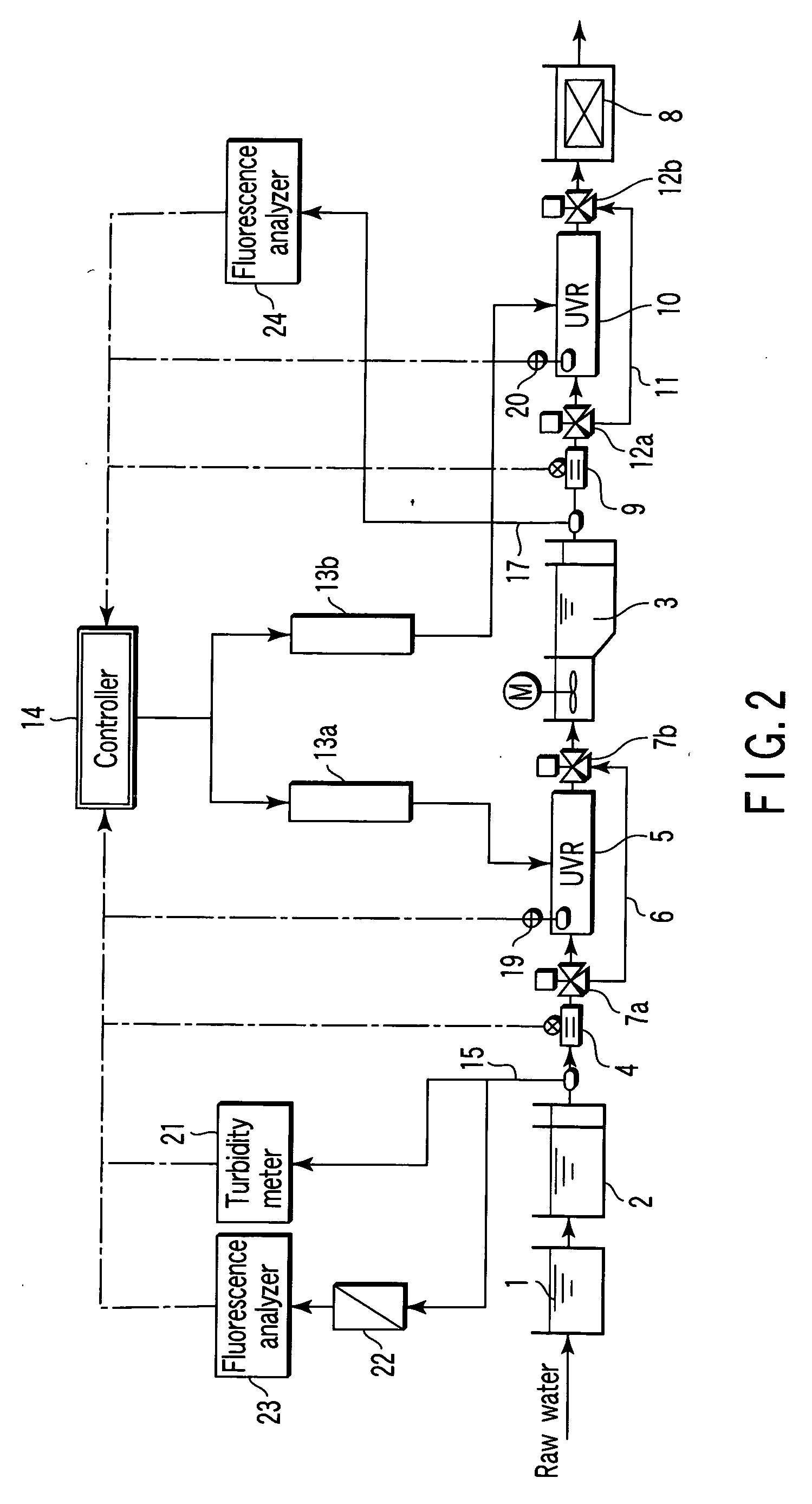
[0078] Hereinafter, the operation and effects of the present embodiment will be explained with reference to FIGS. 2 and 3 to 5.

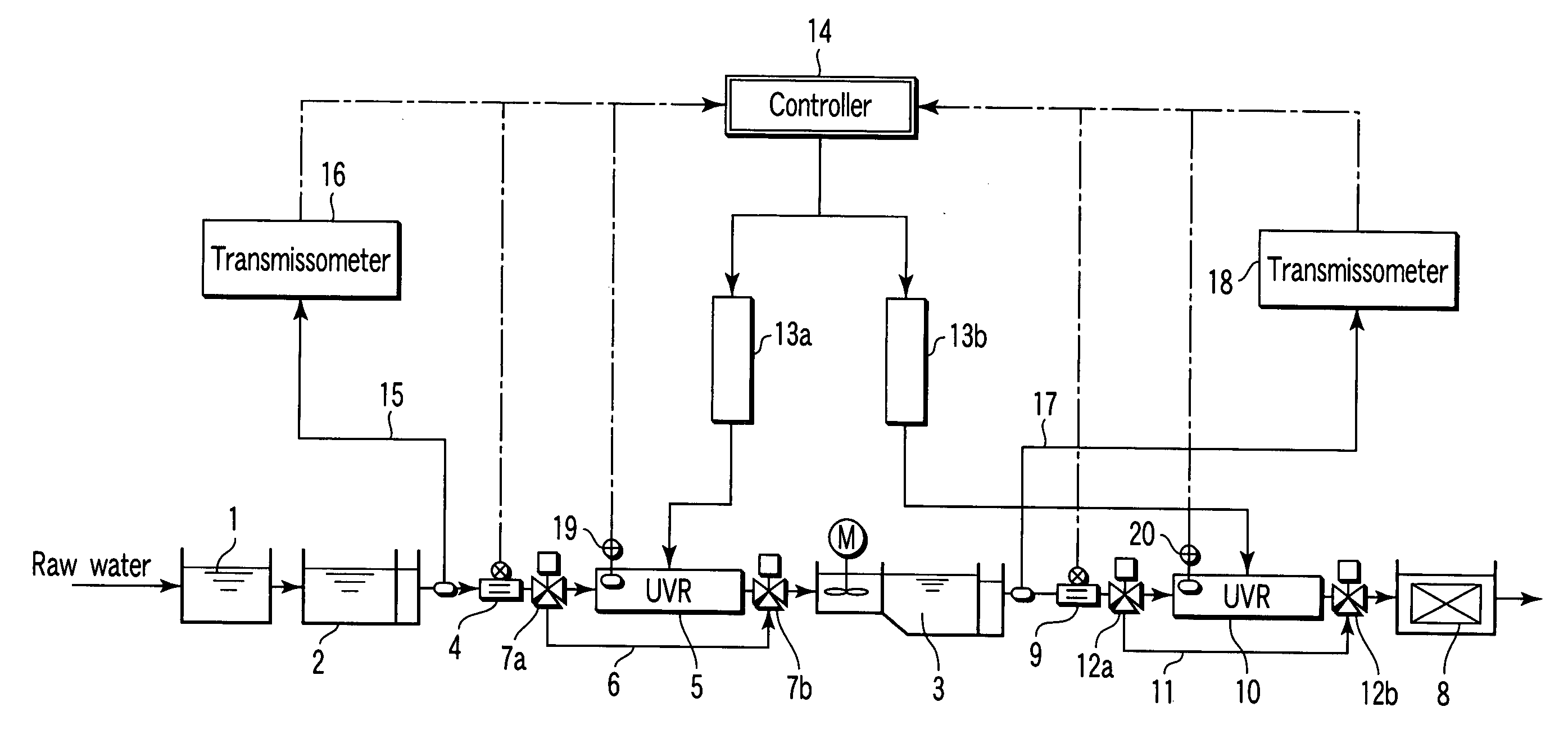
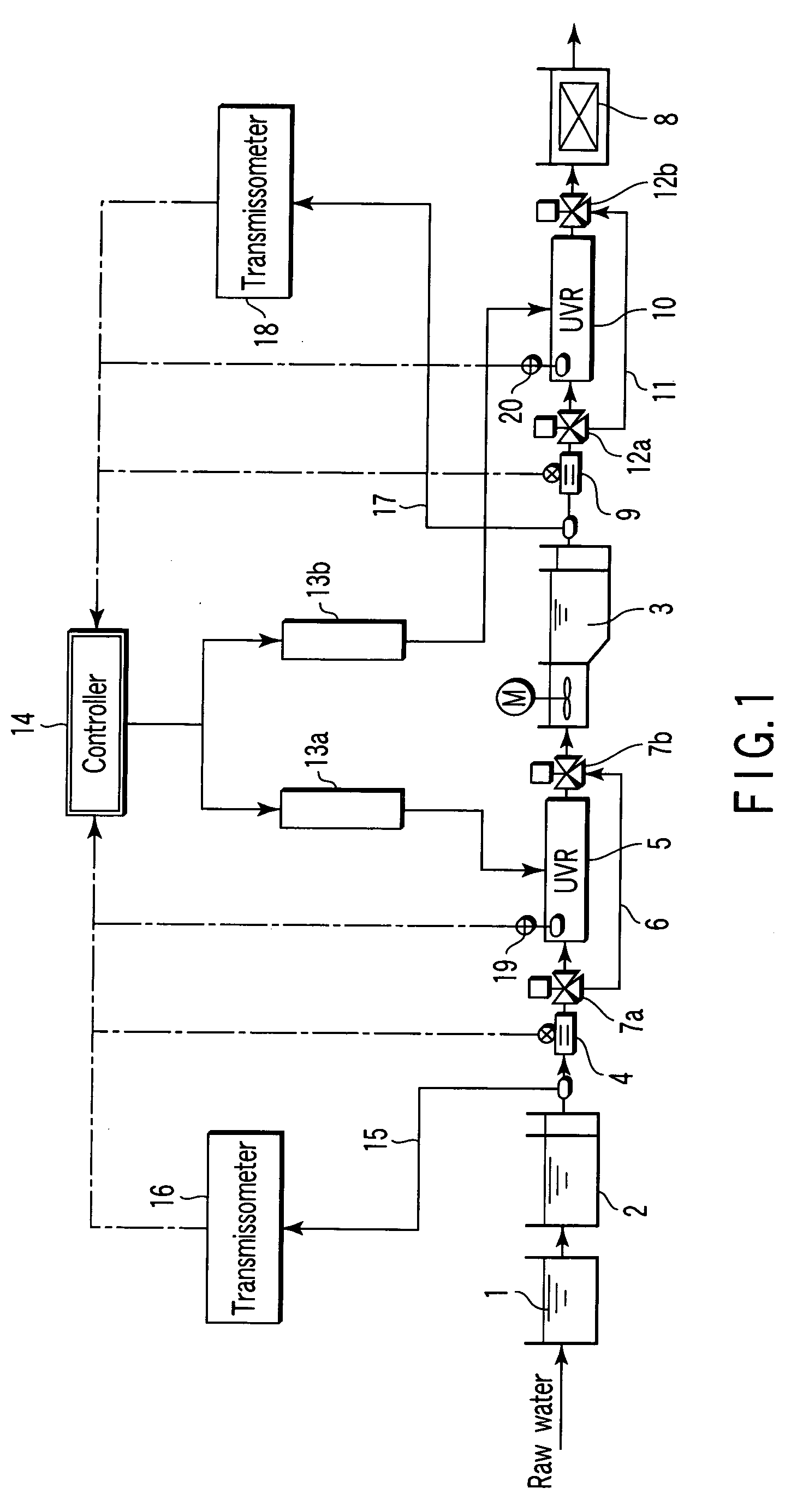
[0079] In general, when ultraviolet penetrates water, the ultraviolet intensity is attenuated by the absorption and scattering of turbidity matters such as particles floating in water, the absorption by organic matters dissolved in water, and the like. More specifically, the ultraviolet intensity decreases as ultraviolet goes away from the radiation surface. The ultraviolet transmittance (%) shows a ratio of ultraviolet penetrating a clearance of 1 cm. Herein, examples of a device for measuring the ultraviolet transmittance include the ultraviolet transmissometers 16, 18 as shown in FIG. 1.

[0080] However, a general ultraviolet transmissometer has a configuration for putting sample water in a quartz glass standard cell to measure an ultraviolet transmittance in batch, or a configuration for causing sample water to...

third embodiment

[0097]FIG. 6 is a block diagram showing major portions of a water treatment system according to a third embodiment of the invention.

[0098] The system according to the present embodiment relates to an ultraviolet radiation control using ultraviolet illuminance meters 19, 20 arranged in a front stage ultraviolet radiation device 5 and a rear stage ultraviolet radiation device 10, respectively. Meanwhile, the same functional components as those of the system according to the first embodiment shown in FIG. 1 are denoted by the same reference numerals, and the detailed description thereof is omitted.

[0099] As shown in FIG. 6, the system according to the present embodiment has the ultraviolet illuminance meters 19, 20 arranged in the front stage ultraviolet radiation device 5 and the rear stage ultraviolet radiation device 10, respectively. Respective measurement results from the ultraviolet illuminance meters 19, 20 are input to a controller 14.

[0100]FIG. 7 is a diagram showing an int...


PUM

PropertyMeasurementUnit
Flow rateaaaaaaaaaa
Turbidityaaaaaaaaaa
Fluorescenceaaaaaaaaaa

Abstract

A water treatment system that performs a water purifying treatment by use of ultraviolet radiation, comprises a front stage ultraviolet radiation device for radiating ultraviolet light in a front stage process in a water purifying treatment process, a rear stage ultraviolet radiation device for radiating ultraviolet light in a rear stage process, and a controller for controlling these ultraviolet radiation devices.

Description

CROSS-REFERENCE TO RELATED APPLICATIONS [0001] This application is based upon and claims the benefit of priority from prior Japanese Patent Applications No. 2005-095943, filed Mar. 29, 2005; and No. 2005-346147, filed Nov. 30, 2005, the entire contents of both of which are incorporated herein by reference. BACKGROUND OF THE INVENTION [0002] 1. Field of the Invention [0003] The present invention relates to an ultraviolet radiation water treatment system for performing a water purifying treatment by use of ultraviolet radiation. [0004] 2. Description of the Related Art [0005] Conventionally, water treatment systems represented by water systems have been operated on the basis of ensuring hygiene by chlorine sterilization. [0006] However, in recent years, there have occurred water system contamination accidents caused by emerging or reemerging pathogenic microbes such as cryptosporidium, giargia and the like. [0007] Further, the mass generation of algae through eutrophication of lakes, ...

Claims


Application Information

Patent Timeline
IPC IPC(8): B01D1/02
CPCC02F2201/326C02F1/325B01D21/0009C02F1/76C02F2209/005C02F2001/007C02F2201/324C02F1/5236B01D21/32C02F1/001B01D21/0012C02F2301/043C02F1/66C02F2209/11
Inventor ABE, NORIMITUSIDE, TAKESHIMATSUSHIRO, TAKESHISUZUKI, HIROYUKIMURAYAMA, SEIICHI
Owner KK TOSHIBA
Why Eureka
Try Eureka