Method for fabricating large dimension bonds using reactive multilayer joining

a multi-layer joining and large-scale technology, applied in the direction of manufacturing tools, soldering devices, explosives, etc., can solve the problems of residual thermal stress in the components, rapid rise in temperature within the rcm, and requiring costly and time-consuming operations, etc., to achieve rapid local heating of materials

Active Publication Date: 2006-10-05
NANOFOIL CORP
View PDF13 Cites 46 Cited by
  • Summary
  • Abstract
  • Description
  • Claims
  • Application Information

AI Technical Summary

Benefits of technology

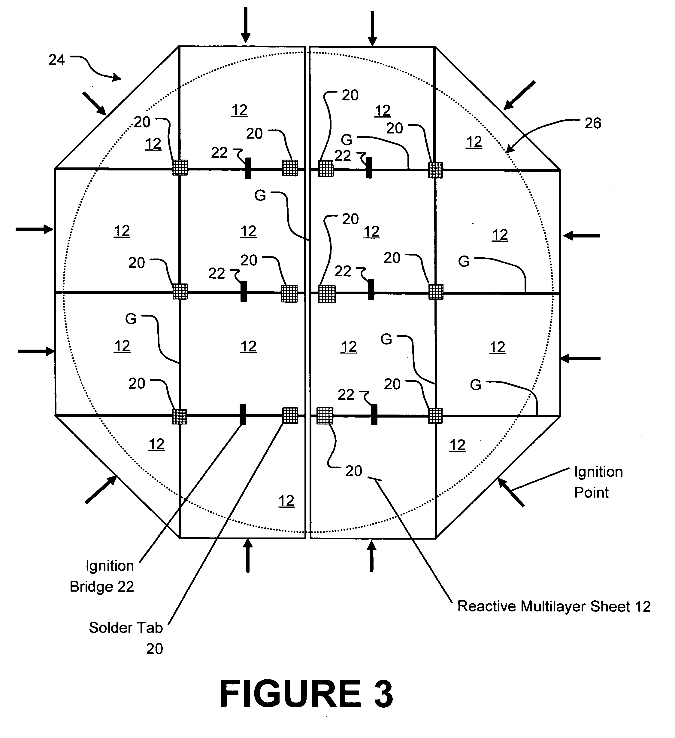
[0012] Briefly stated, the present invention provides a method for joining bodies of component material over regions of large dimensions by disposing a plurality of substantially contiguous RCM sheets between the component material bodies. Each of the substantially contiguous RCM sheets is coupled to at least one adjacent RCM sheet by a bridging material capable of transferring an energetic reaction from one sheet to another. An ignition reaction is initiated in one or more of the RCM sheets and enabled to spread through all remaining sheets via the bridging material, resulting in rapid localized heating of materials adjacent the sheets, which form a bond between the bodies of component material upon cooling.
[0014] In an alternate embodiment of the present invention, a plurality of substantially contiguous RCM sheets disposed between component material bodies to be joined over a region of large dimension are coupled together by structural support tabs of fusible material to enable easy assembly, transport, and positioning of the multiple RCM sheets between the component bodies to be joined.
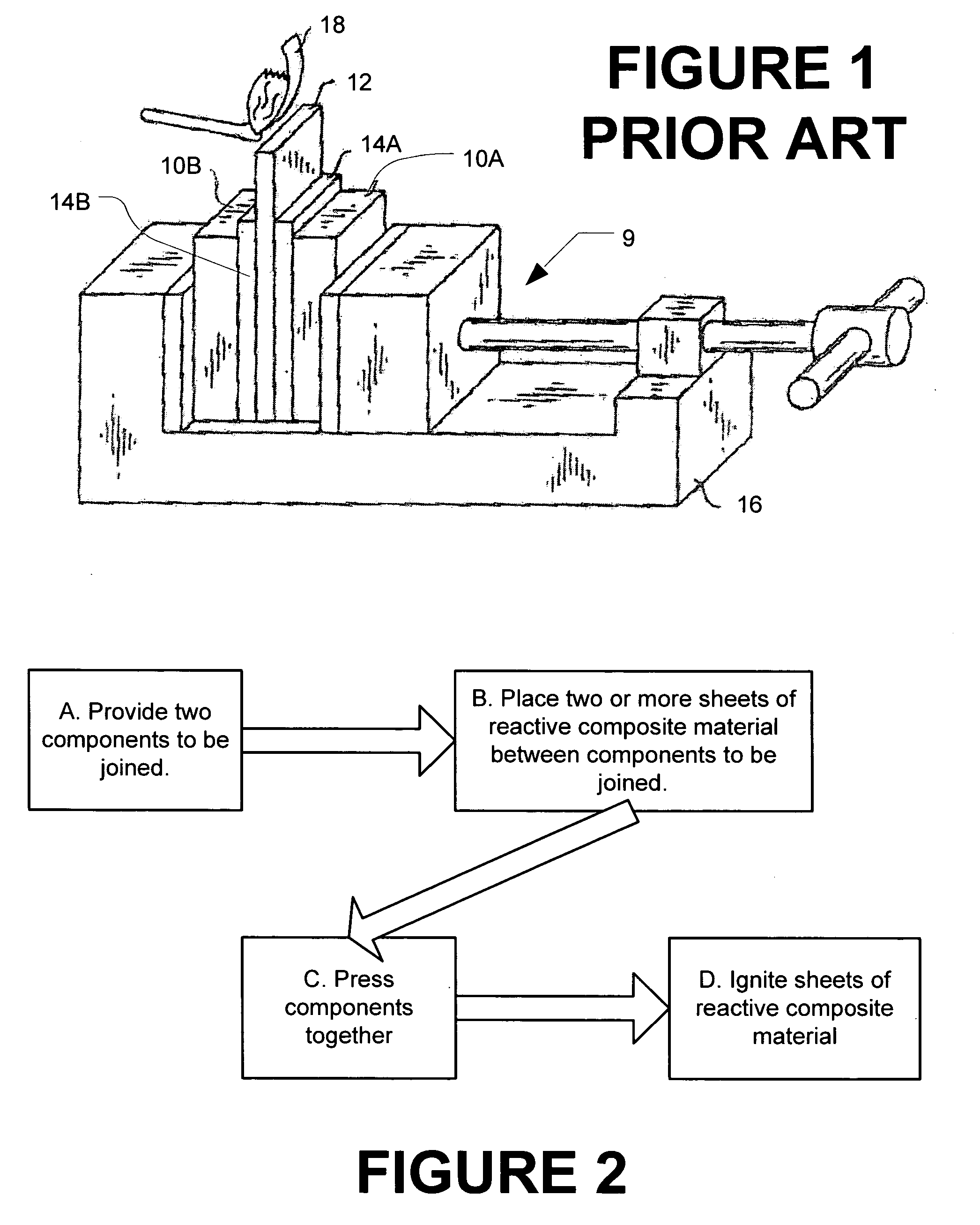
[0017] A method of the present invention for joining bodies of component material over regions of large dimension disposes at least one RCM sheet between the component material bodies. An ignition reaction is initiated at a plurality of ignition points disposed about the RCM sheet, resulting in rapid localized heating of materials adjacent the sheets which form a bond between the bodies of component material upon cooling.
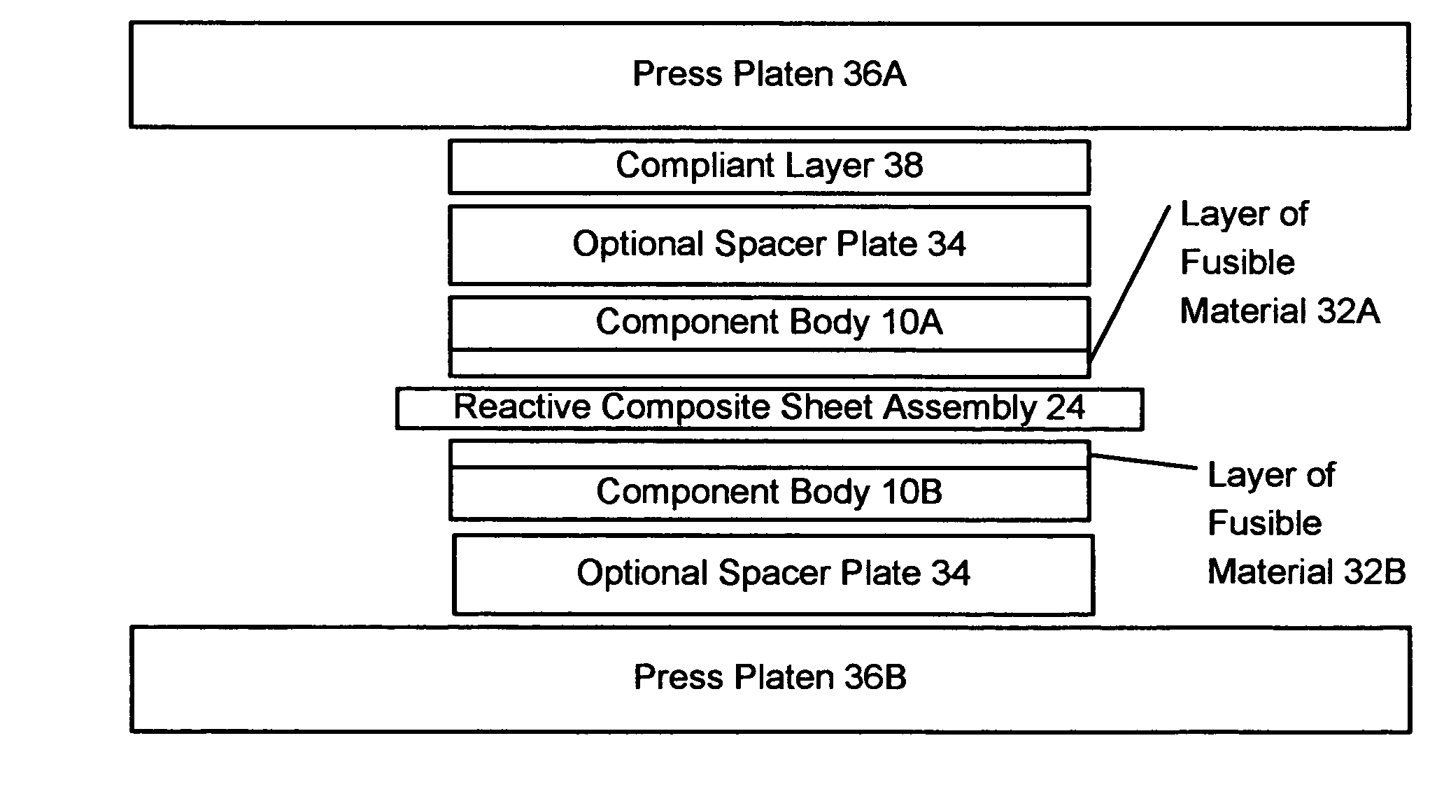
[0018] A variation of the method of the present invention for joining bodies of component material over regions of large dimension disposes at least one RCM sheet between the component material bodies. At least one spacer plate is positioned between an external pressure source and the component bodies. Pressure is applied to the arrangement from the external pressure source, urging the component bodies towards each other to control the formation of a bond between the component bodies following initiation of an ignition reaction in the RCM sheets. The ignition reaction within the RCM sheets results in rapid localized heating of materials adjacent the sheets, which form a bond between the bodies of component material upon cooling.

Problems solved by technology

A self-propagating reaction is initiated within the RCM which results in a rapid rise in temperature within the RCM.
In conventional welding or brazing, temperature-sensitive components can be destroyed or damaged during the process.
Residual thermal stress in the components may necessitate costly and time-consuming operations, such as subsequent anneals or heat treatments.
In contrast, joining with reactive composites subjects the components to little heat and produces only a very local rise in temperature.
In addition, reactive composite joining is fast and results in cost-effective, strong, and thermally conductive joints.
While conventional reactive composite joining works well in joining components over lengths less than about four inches and areas less than about 16 square inches, joining over larger lengths and areas presents particular challenges.
When the lengths and areas become larger, it is increasingly difficult to maintain the desired reaction simultaneity and uniformity from a single ignition point.
In addition, larger joining region dimensions can exceed those of easily fabricated RCM's, requiring multiple pieces of reactive foil to cover the joint surface area.
Even though the joining reaction spreads rapidly through the RCM, not every part of a large surface area joint area may be molten at the same time, possibly resulting in poor bonding between the components.
Moreover, increasing the surface area to be joined presents increasingly stringent requirements for the uniform application of pressure to the components during the joining process.

Method used


Image

  • Method for fabricating large dimension bonds using reactive multilayer joining
  • Method for fabricating large dimension bonds using reactive multilayer joining
  • Method for fabricating large dimension bonds using reactive multilayer joining

Examples


Embodiment Construction

[0038] The following detailed description illustrates the invention by way of example and not by way of limitation. The description enables one skilled in the art to make and use the invention, and describes several embodiments, adaptations, variations, alternatives, and uses of the invention, including what is presently believed to be the best mode of carrying out the invention.

[0039] As used herein, the phrase “large dimension” is used to describe a joint or bonding region and is understood to mean a joint or bonding region having either an area or length which exceeds the area or length of a single sheet of reactive composite material utilized in the joining processes, which is sufficiently large enough that a single propagation wave front from an ignition reaction within a sheet of reactive composite material fails to achieve desired bond characteristics throughout the bonding region, or which exhibits a loading variation between the center and the edges of the joint or bonding...


PUM

PropertyMeasurementUnit
areaaaaaaaaaaa
lengthaaaaaaaaaa
areasaaaaaaaaaa

Abstract

A method for joining component bodies of material over bonding regions of large dimensions by disposing a plurality of substantially contiguous sheets of reactive composite materials between the bodies and adjacent sheets of fusible material. The contiguous sheets of the reactive composite material are operatively connected by an ignitable bridging material so that an igniting reaction in one sheet will cause an igniting reaction in the other. An application of uniform pressure and an ignition of one or more of the contiguous sheets of reactive composite material causes an exothermic thermal reaction to propagate through the bonding region, fusing any adjacent sheets of fusible material and forming a bond between the component bodies.

Description

CROSS-REFERENCE TO RELATED APPLICATIONS [0001] The present application is related to and claims priority from U.S. Provisional Patent Application Ser. No. 60 / 666,179 filed on Mar. 30, 2005, which is herein incorporated by reference.STATEMENT REGARDING FEDERALLY SPONSORED RESEARCH [0002] The United States government has certain rights in this invention pursuant to NSF Award DMI-034972.BACKGROUND OF THE INVENTION [0003] This invention relates to the joining of bodies of material over bonding regions of large dimension using reactive composite materials such as reactive multilayer foils. [0004] Reactive composite joining, such as shown in U.S. Pat. No. 6,534,194 B2 to Weihs et al and in U.S. Pat. No. 6,736,942 to Weihs et al. is a particularly advantageous process for soldering, welding, or brazing materials at room temperature. The process involves sandwiching a reactive composite material (RCM) between two layers of a fusible material. The RCM and the fusible material are then dispos...

Claims


Application Information

Patent Timeline
Patent Type & Authority Applications(United States)
IPC IPC(8): B23K31/02B23K20/08
CPCB23K1/0006B23K20/00B23K20/165B32B15/01C06B45/12Y10T156/10Y10T428/12472Y10T428/12986Y10T428/12222Y10T428/12438H05K3/3494Y10T428/31504Y10T428/31678
Inventor DUCKHAM, ALANNEWSON, JESSE E.BROWN, MICHAEL V.RUDE, TIMOTHY RYANKNIO, OMARHEIAN, ELLEN M.SUBRAMANIAN, JAI S.
Owner NANOFOIL CORP
Why Eureka
Try Eureka