Working method using scanning probe

a scanning probe and working method technology, applied in the direction of mechanical measuring arrangements, mechanical roughness/irregularity measurements, instruments, etc., can solve the problems of low working efficiency, low working efficiency, and inability to obtain a strong cutting force, so as to achieve low working efficiency, strong cutting force, and low working efficiency

Inactive Publication Date: 2006-10-05
HITACHI HIGH TECH SCI CORP
View PDF2 Cites 6 Cited by
  • Summary
  • Abstract
  • Description
  • Claims
  • Application Information

AI Technical Summary

Benefits of technology

[0009] However, the above-mentioned conventional working methods using the scanning probe microscope have following drawbacks. That is, the former working method is a method in which the working is performed by bringing the probe mounted on the distal end of the cantilever into contact with the surface of the sample with the fine force and hence, it is impossible to obtain a strong cutting force whereby the working efficiency is low. Due to this low working efficiency, there exist drawbacks that the working speed is low or a friction is generated due to the continuous contact between the probe and the working surface and the friction shortens a lifetime of the probe.
[0010] Further, in the latter working method, a cutting surface on a surface of the sample and the probe move at a high speed relative to each other. Accordingly, along with the enhancement of the working efficiency, particularly along with the enhancement of the working efficiency when the sample is made of a material having viscoelasticity such as plastic, some improvement is observed from a viewpoint of working speed. However, the working efficiency is still less than optimal and there has been a demand for further improvement of the working efficiency.

Problems solved by technology

That is, the former working method is a method in which the working is performed by bringing the probe mounted on the distal end of the cantilever into contact with the surface of the sample with the fine force and hence, it is impossible to obtain a strong cutting force whereby the working efficiency is low.
Due to this low working efficiency, there exist drawbacks that the working speed is low or a friction is generated due to the continuous contact between the probe and the working surface and the friction shortens a lifetime of the probe.
However, the working efficiency is still less than optimal and there has been a demand for further improvement of the working efficiency.
Further, to consider a case in which an optical mask having the two-layered film structure (MoSi / Glass) which forms molybdenum silicon on glass or the two-layered film structure (Cr / Glass) which forms chromium on glass is worked, since the upper MoSi film or Cr film is harder than the glass which constitutes a substrate, unless the upper film is not uniformly worked, the soft lower glass is cut through the worked portion of the upper film thus arising a drawback that the irregularities of the surface is increased.

Method used


Image

  • Working method using scanning probe
  • Working method using scanning probe
  • Working method using scanning probe

Examples


Embodiment Construction

[0043] Embodiments of a working method using a scanning probe according to the present invention are explained in conjunction with drawings.

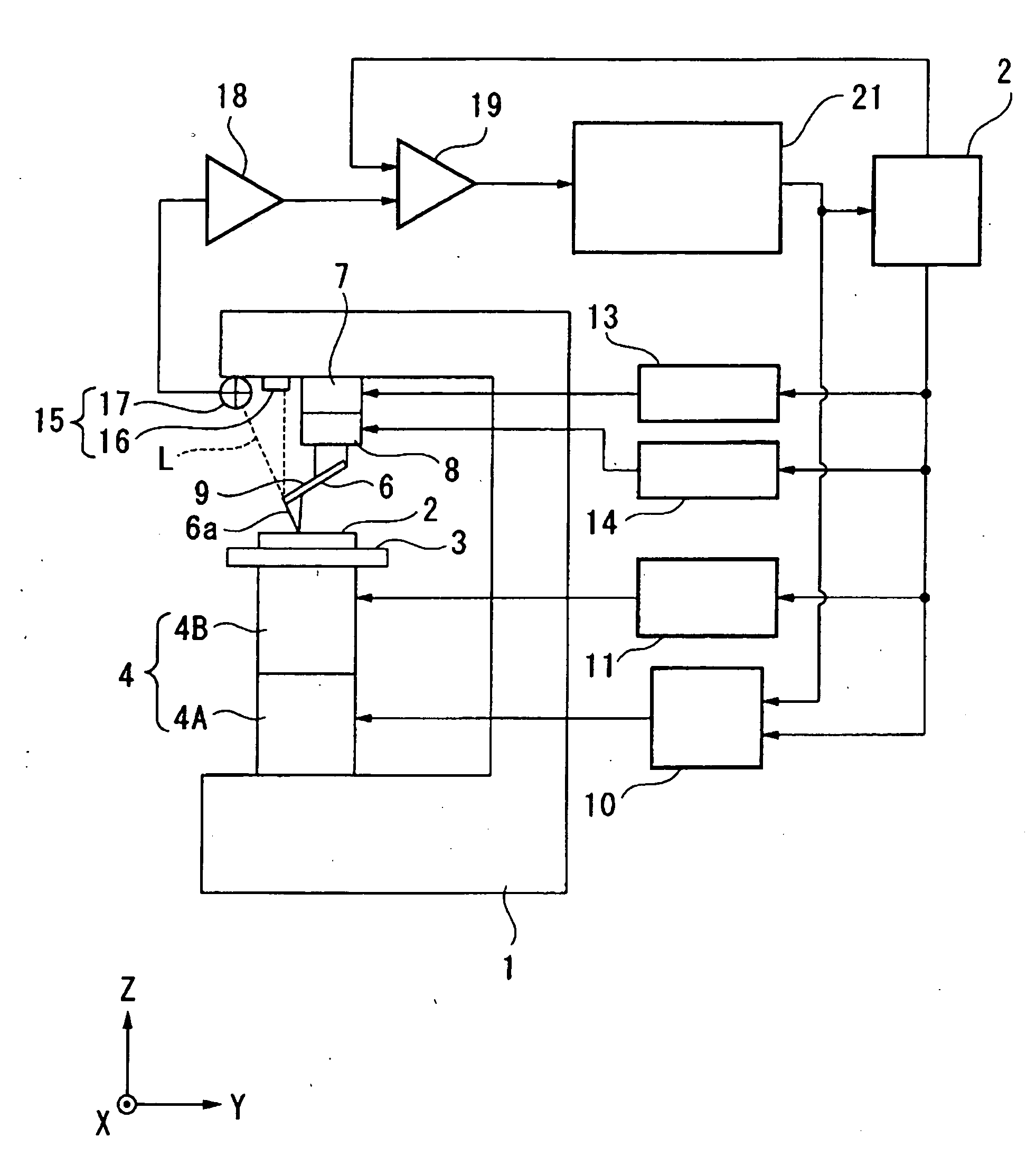
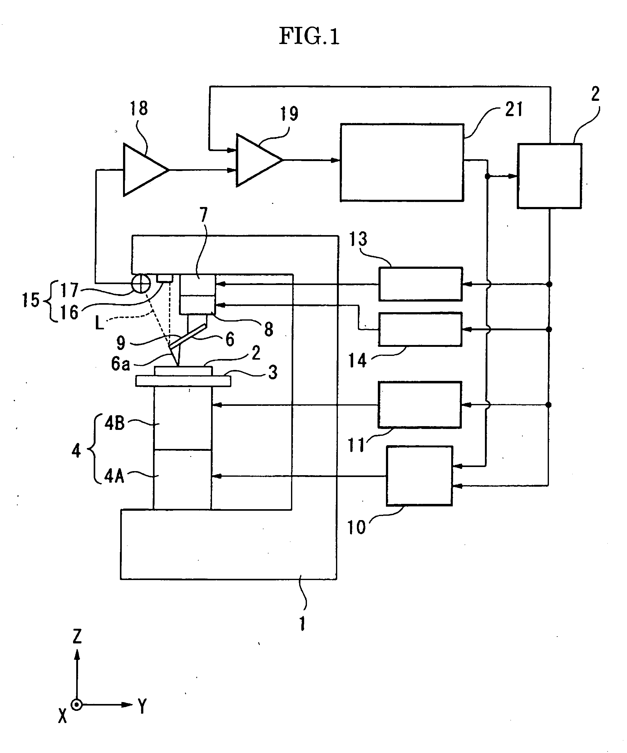
[0044] Before explaining the method of the present invention, a scanning probe microscope which is capable of preferably carrying out the method of the present invention is explained.

[0045] In the drawing, numeral 1 indicates a base frame. On a predetermined portion of a lower portion of the base frame 1, a sample base 3 which mounts a sample 2 which constitutes an object to be worked thereon is mounted in a state that the sample base 3 is movable in the XY directions as well as in the Z direction by way of a scanner 4. The scanner 4 is, for example, constituted of a Z scanner 4A which moves the sample base 3 in the Z direction (vertical direction) and a XY scanner 4B which moves the sample base 3 in the XY directions (horizontal directions). On a predetermined portion of an upper portion of the base frame 1, a probe 6 is supported in a state ...


PUM

PropertyMeasurementUnit
frequencyaaaaaaaaaa
frequencyaaaaaaaaaa
vibration frequencyaaaaaaaaaa

Abstract

The present invention provides a working method using a scanning probe which can enhance a working speed and prolong a lifetime of the probe. The present invention provides the working method using a scanning probe which works a sample by performing the relative scanning of a probe supported on a cantilever on the sample at a predetermined scanning speed. The working method can work the object to be worked while forcibly and relatively vibrating the probe in the direction orthogonal to or parallel to a working surface of the sample at low frequency of 100 to 1000 Hz.

Description

BACKGROUND OF THE INVENTION [0001] 1. Field of the Invention [0002] The present invention relates to a working method using a scanning probe in which a sample is worked using a scanning probe microscope (SPM) which acquires information on a measurement sample by performing the relative scanning of the measurement sample using a probe. [0003] 2. Description of the Related Art [0004] As has been well-known, as an apparatus which measures a sample such as an electron material or the like in a minute region and performs the observation of a surface shape of the sample and the measurement of physical property information of the sample and the like, a scanning probe microscope (SPM) is used. [0005] With respect to the scanning probe microscope, various type of scanning probe microscopes have been proposed. Among these scanning probe microscopes, there exists an atomic force microscope (AFM) referred to as a contact mode which brings a probe mounted on a distal end of a cantilever into con...

Claims


Application Information

Patent Timeline
Patent Type & Authority Applications(United States)
IPC IPC(8): G01N23/00G21K7/00B82B3/00B82Y40/00G01Q30/02G01Q60/24G01Q60/34G01Q80/00
CPCB82Y35/00G01Q60/34G01N23/225
Inventor YASUTAKE, MASATOSHINAKAUE, TAKUYAWATANABE, KAZUTOSHITAKAOKA, OSAMUUEMOTO, ATSUSHIWATANABE, NAOYASHIKAKURA, YOSHITERU
Owner HITACHI HIGH TECH SCI CORP
Why Eureka
Try Eureka