Check patentability & draft patents in minutes with Patsnap Eureka AI!

Circuit arrangement and method for controlling a pulsed power supply

Active Publication Date: 2006-10-05
ABL IP HLDG
View PDF6 Cites 3 Cited by
  • Summary
  • Abstract
  • Description
  • Claims
  • Application Information

AI Technical Summary

Benefits of technology

[0010] One object of the present invention is to provide a circuit arrangement for controlling a pulsed power supply which avoids the abovementioned disadvantages from the prior art, i.e. the invention provides an increase in the control speed without any amplification of the control oscillations.
[0011] One further aspect of the present invention is to provide a circuit arrangement for controlling a pulsed power supply which makes possible the advantageous use of a microcontroller or a digital logic unit.
[0012] One further aspect of the present invention is to provide a circuit arrangement for controlling a pulsed power supply which is suitable both for the so-called “continuous mode”, in which the buck inductor current does not become zero, and for the so-called “discontinuous mode”, in which the buck inductor current in the meantime becomes zero.

Problems solved by technology

The control speed cannot be increased as desired, since otherwise the stability of the control is no longer ensured.
An increase in the control speed, for example by increasing the so-called closed-loop gain, is always detrimental to stability in the prior art and thus leads to increased control oscillations.
In the prior art, variations in the voltage of the energy feed source thus in principle lead to variations in the controlled variable, i.e. variations in the voltage of the energy feed source cannot be completely compensated for.
Better compensation can in turn only take place to the detriment of stability.

Method used


Image

  • Circuit arrangement and method for controlling a pulsed power supply
  • Circuit arrangement and method for controlling a pulsed power supply
  • Circuit arrangement and method for controlling a pulsed power supply

Examples


Embodiment Construction

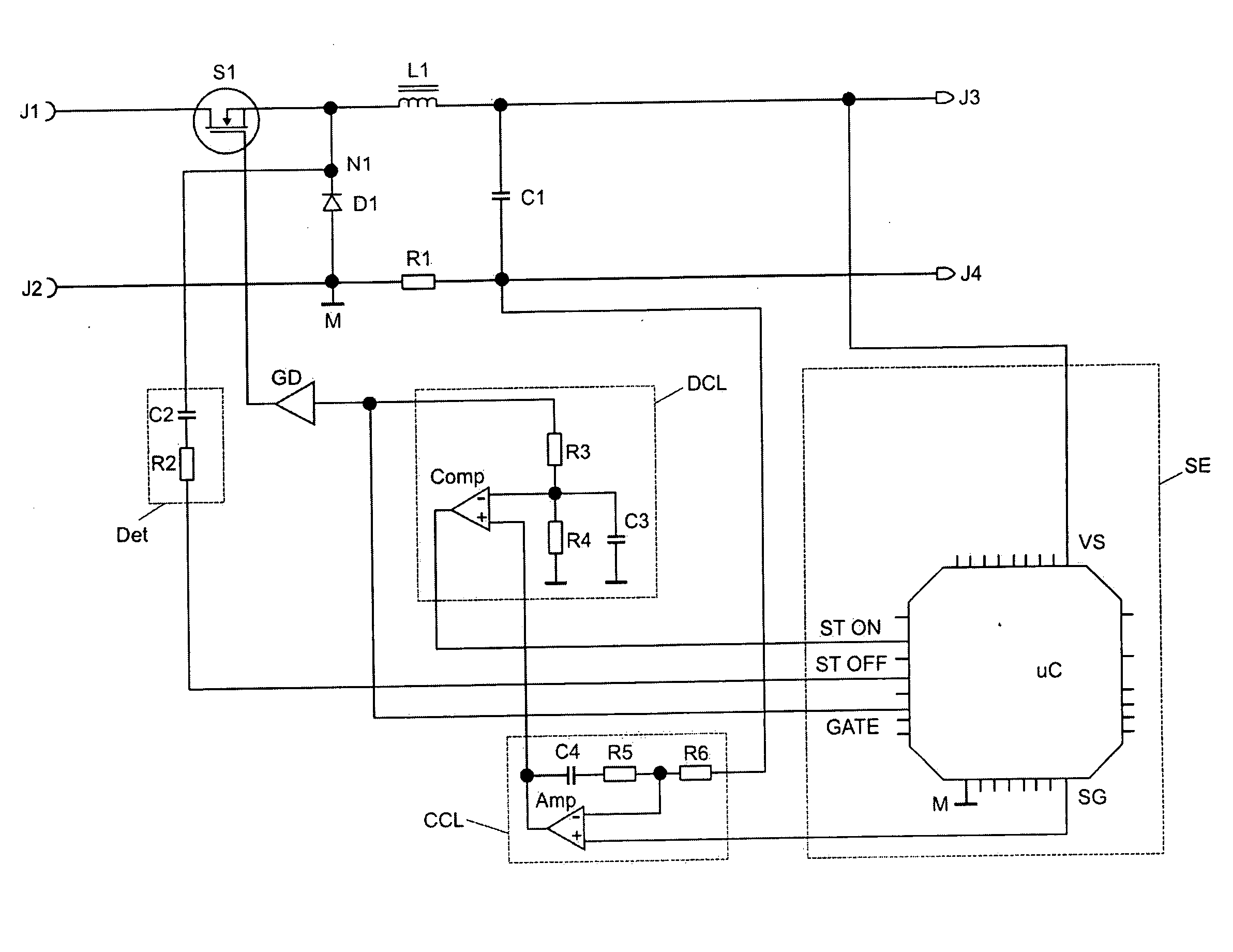
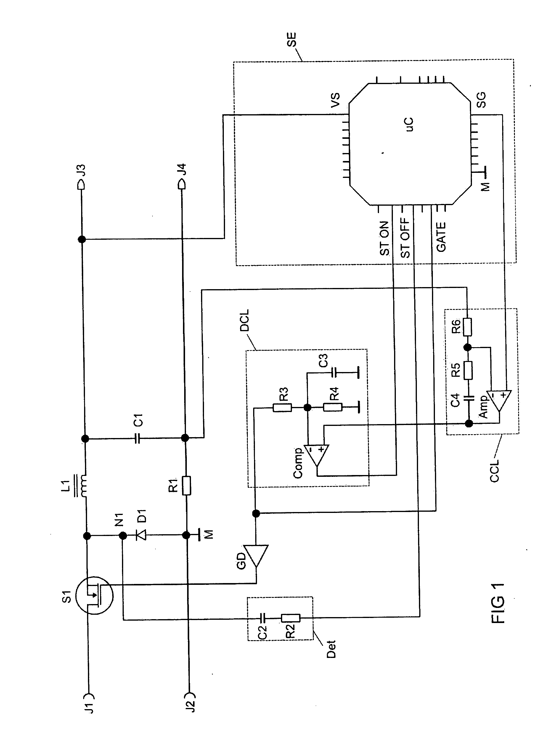
[0038]FIG. 1 shows an exemplary embodiment of a circuit arrangement according to the invention having a buck converter. An energy feed source can be connected to the connection terminals J1 and J2. This may be, for example, a so-called “power factor control” stage.

[0039] The buck converter makes available, for a load, a controlled voltage, a controlled current or a controlled power at the connections J3 and J4, depending on the programming of a microcontroller uC. For example, the load may be a discharge lamp.

[0040] The buck converter in a known manner comprises an electronic switch S1, a diode D1, a buck inductor L1 and a storage capacitor C1.

[0041] S1 and L1 are connected as a series circuit between J1 and J3 via a node N1. S1 is in the form of a MOSFET in FIG. 1. Other electronic switches such as IGBTs or bipolar transistors can also be used. J2 is connected to a ground potential M. The diode D1 is connected between N1 and the ground potential M. The storage capacitor C1 is co...


PUM


Abstract

Circuit arrangement for controlling a pulsed power supply having improved dynamics compared with conventional “current mode” controllers. According to the invention, the gate signal of a switch (S1) is integrated. As soon as this integral value exceeds the output signal of a control amplifier (CCL), the switch (S1) is switched off again. The circuit arrangement is highly suitable for economically apportioning analog switching elements and functions which are implemented by a microcontroller (uC).

Description

FIELD OF THE INVENTION [0001] The invention relates to a circuit arrangement for controlling a pulsed power supply. The invention also relates to a method for controlling a pulsed power supply. BACKGROUND OF THE INVENTION [0002] Pulsed power supplies are generally known. They are used for matching electrical energy provided to the requirements of a load. This is, for example, matching of the voltage level or provision of a controlled voltage or current source. Pulsed power supplies essentially comprise at least one electronic switch and energy stores such as inductors and capacitors. [0003] In common use is the so-called buck converter, which is used, in a representative manner for other converters, as the basis for describing the present invention. Buck converters are usually used for providing a voltage source which has a voltage which is lower than the voltage of the feed source. Buck converters, however, are also used to operate a load from a voltage source, which load requires ...

Claims


Application Information

Patent Timeline
IPC IPC(8): G05F1/00H02M3/156H02M3/157
CPCH02M3/156H02M1/08H02M3/157H02M3/155
Inventor HUBER, ANDREASREITER, BERNHARD
Owner ABL IP HLDG
Features
  • R&D
  • Intellectual Property
  • Life Sciences
  • Materials
  • Tech Scout
  • Unparalleled Data Quality
  • Higher Quality Content
  • 60% Fewer Hallucinations
Learn More