Coding device and decoding device

a technology which is applied in the field of coding device and decoding device, can solve the problems of large circuit size, 20/21 qmtr code, and general difficulty in construction, and achieve the effect of simple circui

Inactive Publication Date: 2006-10-05
WESTERN DIGITAL TECH INC
View PDF6 Cites 0 Cited by
  • Summary
  • Abstract
  • Description
  • Claims
  • Application Information

AI Technical Summary

Benefits of technology

[0011] To raise the performance of a disk apparatus, it is preferable to maximize the number of data bits to be coded at a time or the amount of data to be processed at a time. As described earlier, however, it is generally very difficult to construct, for example, a 20 / 21 QMTR code to encode 20-bit data into 21-bit data. In addition, even if such a code is constructed, this would require a large scale circuit. It is not considered practical to design a circuit capable of appropriately performing such long bit-length coding as 20 / 21 QMTR coding.
[0012] The present invention has been made in view of the above-mentioned situation. It is a feature of the present invention to allow relatively simple circuits to provide a coding device capable of coding longer bit-length data suitably for disk apparatus and a decoding device capable of decoding the data coded by the coding device.

Problems solved by technology

As described earlier, however, it is generally very difficult to construct, for example, a 20 / 21 QMTR code to encode 20-bit data into 21-bit data.
In addition, even if such a code is constructed, this would require a large scale circuit.
It is not considered practical to design a circuit capable of appropriately performing such long bit-length coding as 20 / 21 QMTR coding.

Method used


Image

  • Coding device and decoding device
  • Coding device and decoding device
  • Coding device and decoding device

Examples


Embodiment Construction

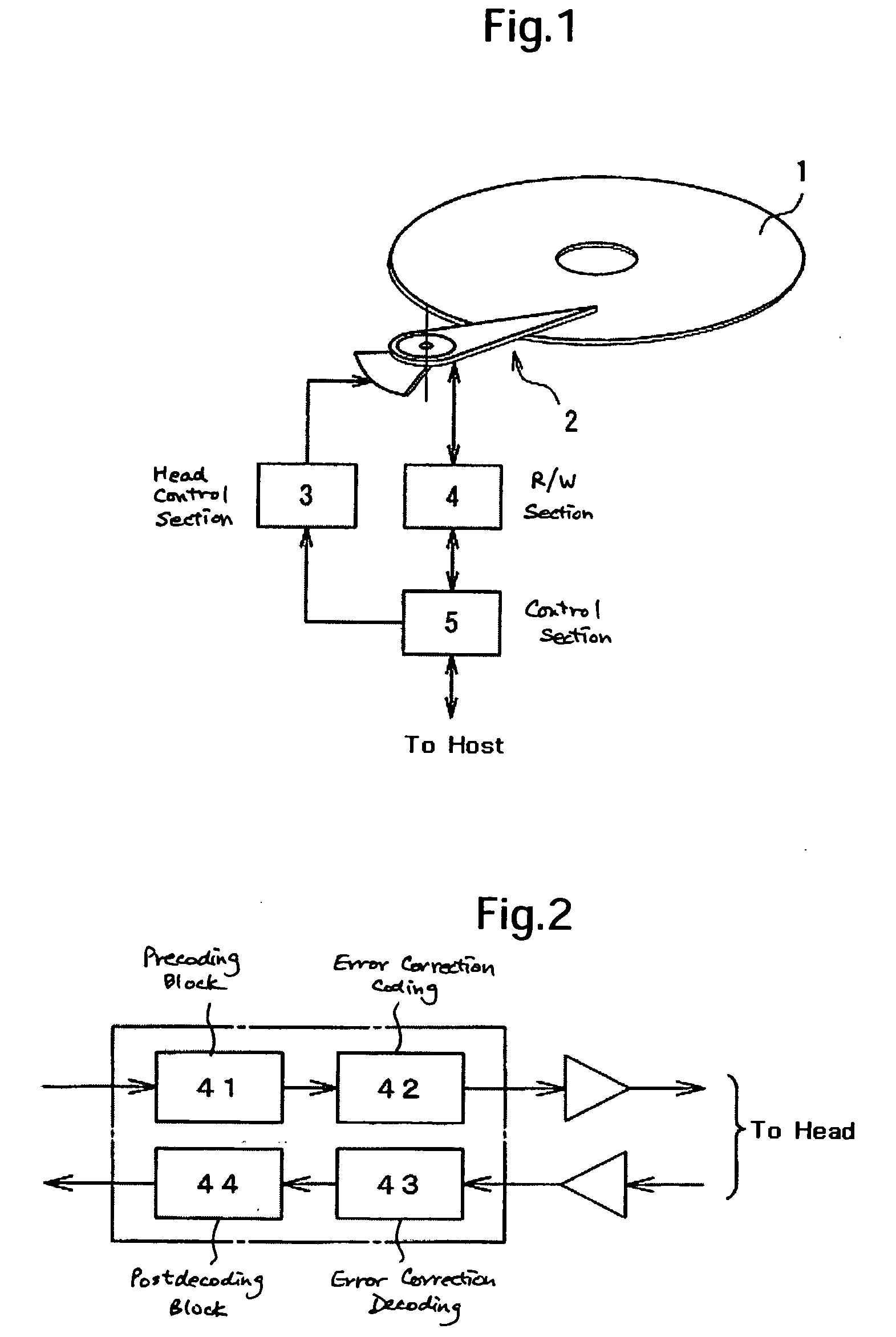
[0024] The following will describe embodiments of the present invention with reference to the drawings. A coding device and a decoding device of the embodiments are incorporated in a disk apparatus. A specific example of a disk apparatus incorporating a coding device and a decoding device of the present embodiments comprises a disk medium 1, a head assembly 2, a head control section 3, a read write (RW) section 4 and a control section 5 as shown in FIG. 1. FIG. 1 shows the general configuration of the disk apparatus.

[0025] Having a magnetic head, the head assembly 2 relatively moves on the surface of the disk medium 1 to perform access to the disk medium 1 in order to magnetically reproduce / record (read / write) information.

[0026] The head control section 3 controls the head assembly 2 to move the magnetic head on the disk medium 1.

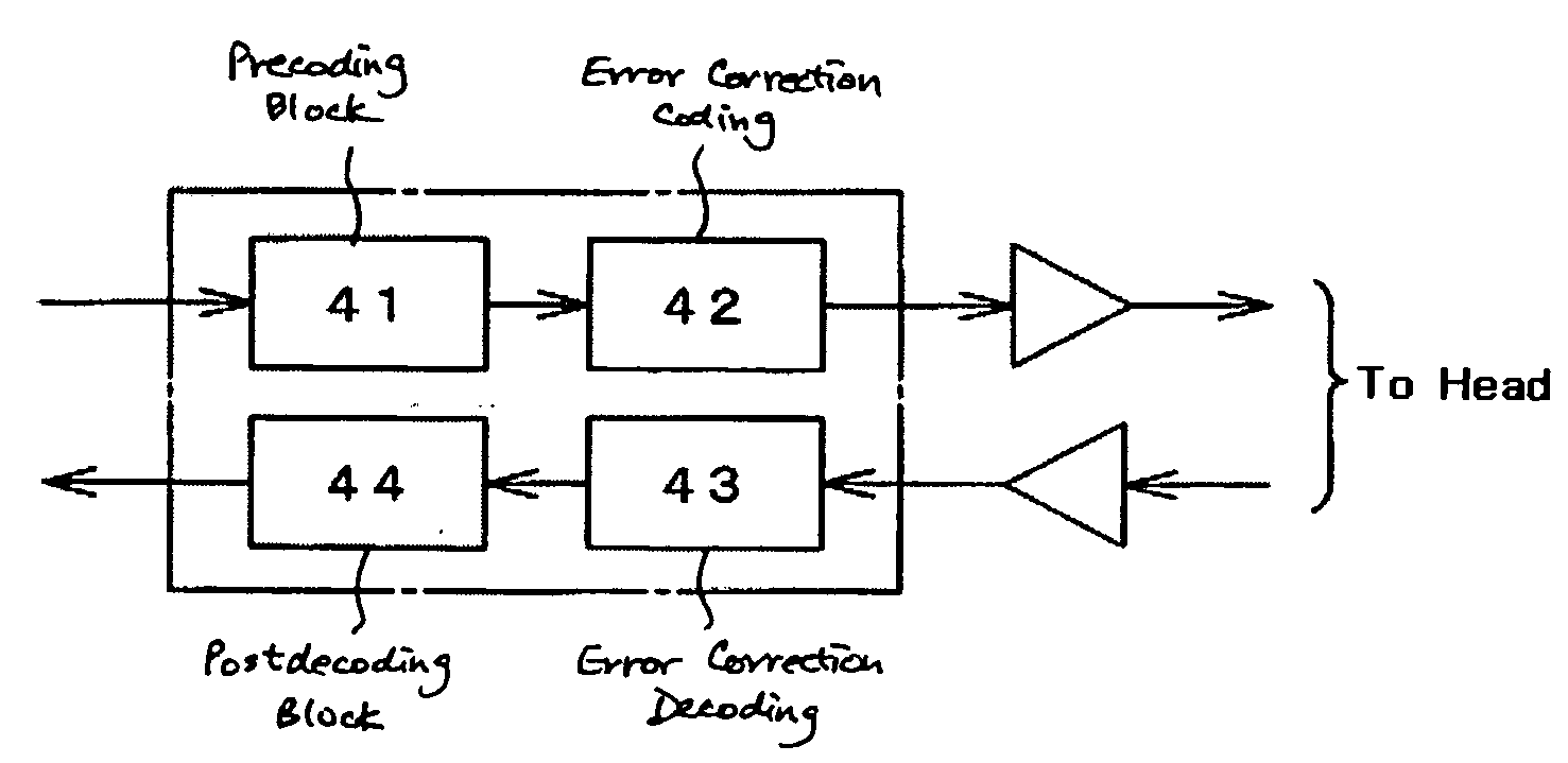
[0027] The RW section 4 codes the signal incoming from the control section 5 and outputs the coded information to the magnetic head of the head assembly...


PUM


Abstract

Embodiments of the invention allow relatively simple circuits to provide a coding device capable of coding longer bit-length data suitably for disk apparatus and a decoding device capable of decoding the data coded by the coding device. In one embodiment, a coding device comprises: a coder which, based on an M bits code string, produces an (M+1) bits coded string where each of the plural bits which may appear in the M bits code string is limited in run length; a preprocessor which produces an M bits code string by removing (N-M) bits respectively from predefined (N-M) positions of an incoming N bits code string and outputs the M bits code string to the coder; and a postprocessor which produces and outputs an (N+1) bits code string by inserting the (N-M) bits, which are removed by the preprocessor, into predefined (N-M) respective insertion positions of the (M+1) bits coded string output from the coder.

Description

CROSS-REFERENCES TO RELATED APPLICATIONS [0001] This application claims priority from Japanese Patent Application No. JP2005-099829, filed Mar. 30, 2005, the entire disclosure of which is incorporated herein by reference. BACKGROUND OF THE INVENTION [0002] The present invention relates to a coding device and decoding device for use in hard disk and other storage apparatus. [0003] Recently, the so-called PRML (Partial Response Maximum Likelihood) system is widely used for recording and reproducing in magnetic disk and other storage apparatus. In the PRML system, a partial response (PR) channel is combined with Viterbi coding. [0004] The reproduction circuit is assumed as a channel with, for example, the Partial Response Class 4 (PR4) transfer function. The PR4 is expressed by G(D)=(1−D)(1+D) wherein D is the delay operator. For higher density recording, it is known that higher order partial responses such as Enhanced Partial Response Class 4 (EPR4) of G(D)=(1−D)(1+D)2, Enhanced EPR4 ...

Claims


Application Information

Patent Timeline
Patent Type & Authority Applications(United States)
IPC IPC(8): H03M7/34
CPCG11B20/10175G11B20/10296G11B20/1426H03M5/145G11B20/1866G11B2220/2516G11B20/1833
Inventor TAKASHI, TERUMIWATANABE, YOSHIJUIZUMITA, MORISHIITOU, YASUYUKI
Owner WESTERN DIGITAL TECH INC
Why Eureka
Try Eureka