Lithographic apparatus and device manufacturing method utilizing data filtering

a technology of data filtering and lithographic apparatus, which is applied in the direction of optical devices, photomechanical devices, instruments, etc., can solve the problems of affecting the quality of the device to be manufactured, the inability to predict the cd properties of the pattern after post-exposure processing, and the inability to apply cd bias in this way only uniformly

Inactive Publication Date: 2006-10-05
ASML NETHERLANDS BV
View PDF23 Cites 25 Cited by
  • Summary
  • Abstract
  • Description
  • Claims
  • Application Information

AI Technical Summary

Benefits of technology

[0015] According to one embodiment of the present invention, there is provided a lithographic apparatus comprising a projection system, a patterning device, a low pass filter, and a data manipulation device. The projection system project a beam of radiation onto a substrate as an array of sub-beams of radiation. The patterning device modulates the sub-beams of radiation to substantially produce a requested dose pattern on the substrate. The dose pattern is built up from an array of spot exposures in which at least neighboring spot exposures are imaged incoherently with respect to each other and e

Problems solved by technology

Either or both of these variations can have a negative influence on the quality of a device to be manufactured.
Although the CD of the dose pattern can be defined quite accurately prior to exposure, it is more difficult to predict the CD properties of the pattern after post-exposure processing.
However, CD biasing in this way can only be applied uniformly and in a circularly symmetrical fashion over the surface of the substrate.
Variation in the position of the substrate surface relative to the plane of best focus can cause deterioration in the quality of the image formed on the substrate.
Complex servo and control systems can be provided to translate and/or tilt the substrate table and/or projection system in order to keep the substrate near the plane

Method used


Image

  • Lithographic apparatus and device manufacturing method utilizing data filtering
  • Lithographic apparatus and device manufacturing method utilizing data filtering
  • Lithographic apparatus and device manufacturing method utilizing data filtering

Examples


Embodiment Construction

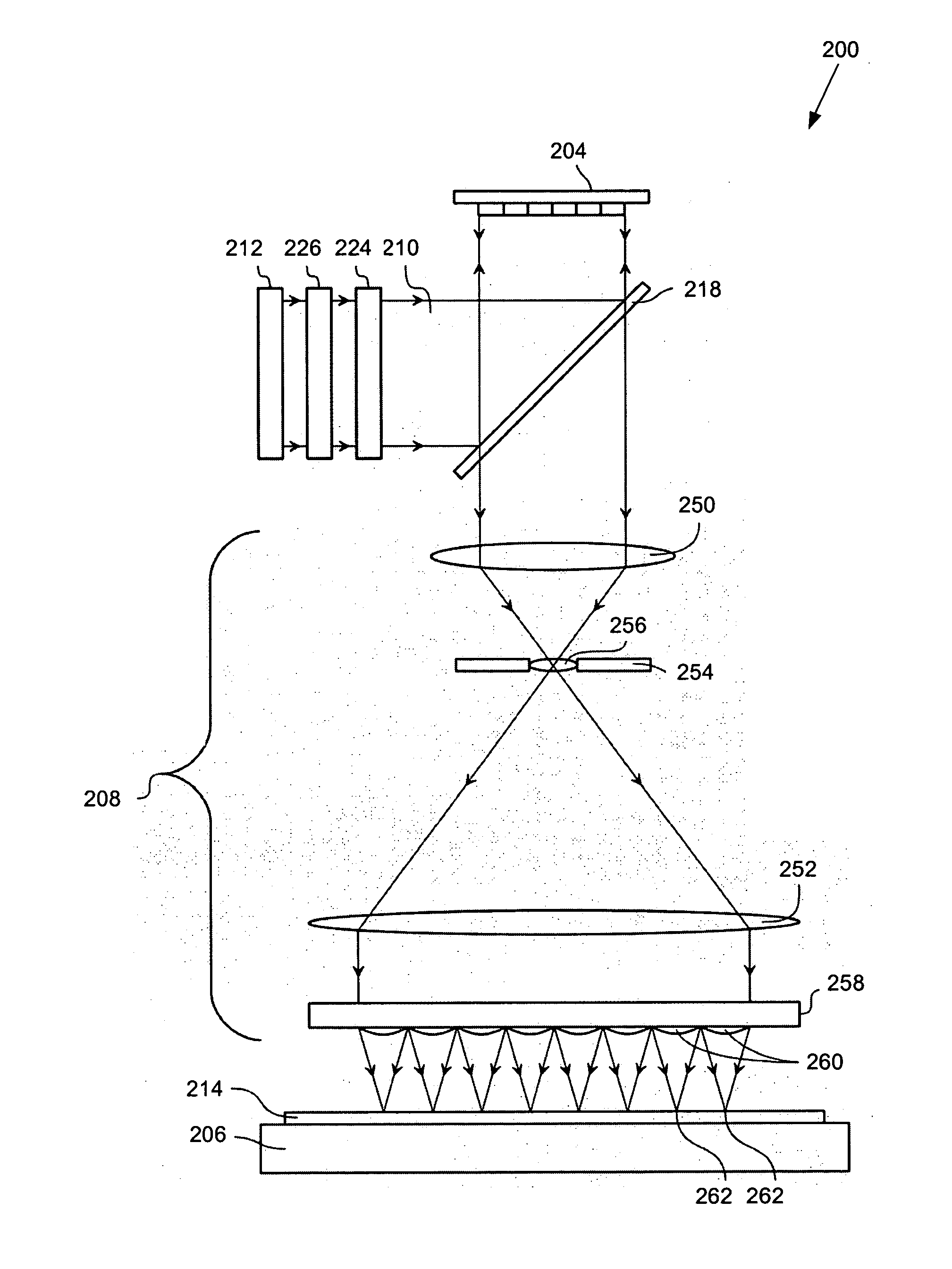
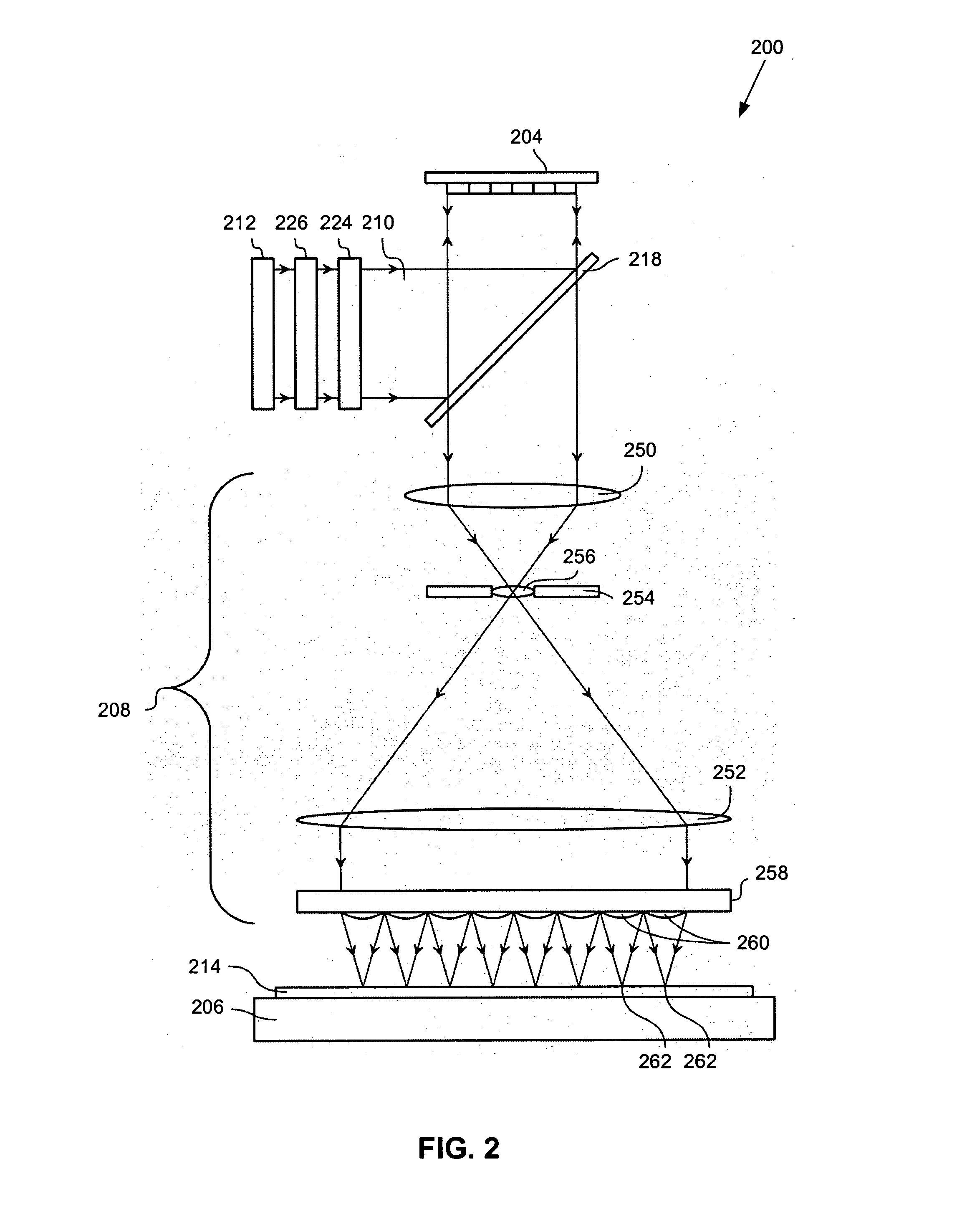
[0044] In one embodiment of the present invention provides a blazing portion in a section of an array of individually controllable elements (e.g., a contrast device).

[0045] All the elements in the blazing portion have their individually controllable elements positioned at a same angle, which forms the blazing portion. In one example, this can be accomplished through use of a super-pixel. The blazing portion is used to increase light intensity in a first diffraction order a beam modulated by the array. This is accomplished by substantially eliminating a negative first diffraction order modulated beam, such that the positive first diffraction order modulated beam has, in effect, about equal to or more than twice the intensity compared to a typical positive first diffraction order modulated beam. For example, when using a λ / 4 tip deflection, substantially all of the incident light is reflected in the first diffraction order.

[0046] In another embodiment, instead of a first diffraction...


PUM


Abstract

An apparatus and method are used to form patterns on a substrate. The comprise a projection system, a patterning device, a low-pass filter, and a data manipulation device. The projection system projects a beam of radiation onto the substrate as an array of sub-beams of radiation. The patterning device modulates the sub-beams of radiation to substantially produce a requested dose pattern on the substrate. The low-pass filter operates on pattern data derived from the requested dose pattern in order to form a frequency-clipped target dose pattern that comprises only spatial frequency components below a selected threshold frequency. The data manipulation device produces a control signal comprising spot exposure intensities to be produced by the patterning device, based on a direct algebraic least-squares fit of the spot exposure intensities to the frequency-clipped target dose pattern. In various examples, filters for pattern sharpening, image log slope control, and/or CD biasing can also be used.

Description

BACKGROUND [0001] 1. Field [0002] The present invention relates to a lithographic apparatus and a method for manufacturing a device. [0003] 2. Related Art [0004] A lithographic apparatus is a machine that applies a desired pattern onto a substrate, usually onto a target portion of the substrate. A lithographic apparatus can be used, for example, in the manufacture of flat panel displays, integrated circuits (ICs), micro-electro-mechanical-systems (MEMS), and other devices involving fine structures. In a conventional apparatus, a contrast device or a patterning device, which can be referred to as a mask or a reticle, can be used to generate a circuit pattern corresponding to an individual layer of a flat panel display or other device. This pattern can be transferred onto a target portion (e.g., comprising part of one or several dies) on a substrate (e.g., a glass plate). Transfer of the pattern is typically via imaging onto a layer of radiation-sensitive material (e.g., resist) provi...

Claims


Application Information

Patent Timeline
IPC IPC(8): G03B27/72
CPCG03F7/70291G03F7/70191G03F7/70508G03F7/70433
Inventor TINNEMANS, PATRICIUS ALOYSIUS JACOBUSBASELMANS, JOHANNES JACOBUS MATHEUS
Owner ASML NETHERLANDS BV
Why Eureka
Try Eureka