Magnetic disk apparatus

a magnetic disk and apparatus technology, applied in the field of magnetic disk apparatuses, can solve the problems of increasing current density, increasing noise in the reproduced signal, and prone to reading errors, so as to reduce the noise caused by the spin transfer effect, improve the recording density of the magnetic disk apparatus, and remove the effect of noise components

Inactive Publication Date: 2006-10-05
KK TOSHIBA
View PDF12 Cites 3 Cited by
  • Summary
  • Abstract
  • Description
  • Claims
  • Application Information

AI Technical Summary

Benefits of technology

[0011] With such means, the low-frequency components of the reproduced signal are suppressed. Since the noise components caused by the spin transfer effect are biased toward the low-frequency side, the noise components can be removed effectively with the above configuration, which makes it possible to improve the recording density of the magnetic disk apparatus more.
[0012] According to the present invention, noise caused by the spin transfer effect can be reduced and the recording density of the magnetic disk apparatus can be improved more.

Problems solved by technology

Therefore, as the head size reduces, the cross-sectional area of the film surface which bias current crosses decreases, resulting in an increase in the current density.
This phenomenon becomes pronounced and noise in the reproduced signal becomes larger, making reading errors liable to occur.
As described above, in the current perpendicular to plane magnetic head, as the size of the head reduces, the effect of noise caused by the spin transfer effect becomes greater, making reading errors liable to occur.

Method used


Image

  • Magnetic disk apparatus
  • Magnetic disk apparatus
  • Magnetic disk apparatus

Examples


first embodiment

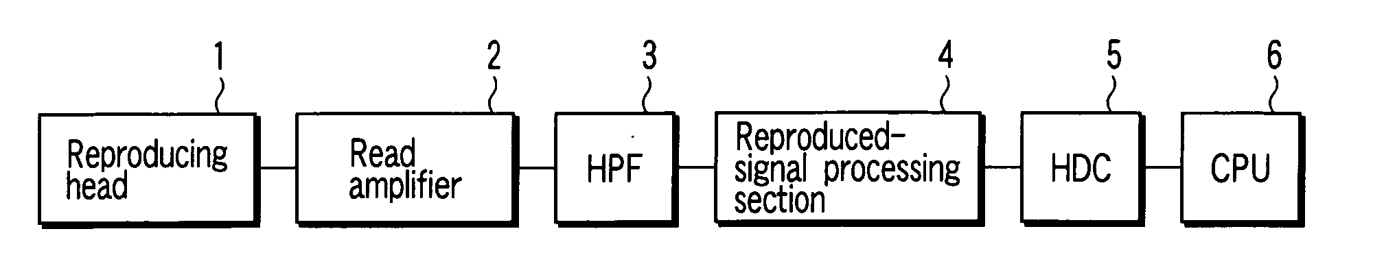
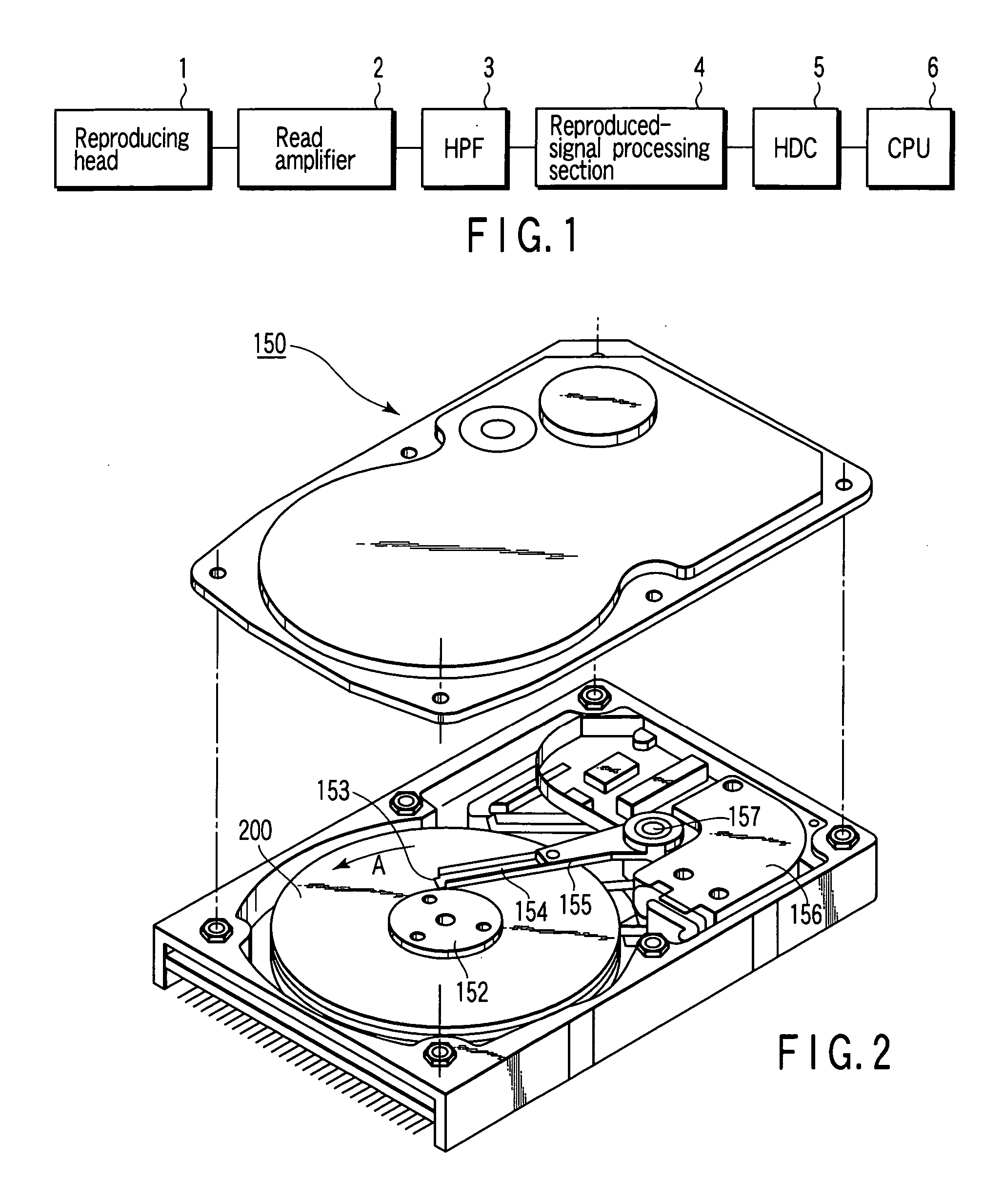
[0026] According to an embodiment, FIG. 1 is an exemplary functional block diagram of a first embodiment of a magnetic disk apparatus according to the present invention. In FIG. 1, a reproducing head 1, which is used in proximity to a magnetic disk medium (not shown), and outputs a reproduced signal whose waveform corresponds to the magnetic field at the surface of the medium. The reproduced signal is amplified by a read amplifier 2. Its low-frequency components are suppressed by a high-pass filter (HPF) 3. The low-frequency-suppressed reproduced signal is input to a reproduced-signal processing section 4, which reproduces the data on the disk medium. The reproduced-signal processing section 4 is connected to a hard disk controller (HDC) 5 and a CPU (Central Processing Unit) 6. The hard disk controller 5 and CPU 6 perform a reproduced data error correcting process and positioning control of the reproducing head 1.

[0027] The reproducing head of FIG. 1 includes a magnetoresistive eff...

second embodiment

[0039]FIG. 6 is an exemplary functional block diagram of a second embodiment of a magnetic disk apparatus according to the present invention. The magnetic disk apparatus of FIG. 6 is such that the characteristic of the high-pass filter 3 of FIG. 1 is set suitably so as to function as a differentiating circuit. That is, in FIG. 6, a high-pass filter and differentiating circuit 7 is inserted between the read amplifier 2 that amplifies the reproduced signal from the reproducing head 1 and the reproduced-signal processing section 4. The high-pass filter and differentiating circuit 7 is obtained by setting the cut-off frequency of the high-pass filter 3 (FIG. 1) to a value that enables a reduction in noise caused by the spin transfer effect and the generation of differential waveforms to be compatible with each other.

[0040] The configuration of FIG. 6 can be used suitably in a perpendicular recording magnetic disk apparatus. As is well known, the waveform of the reproduced signal in the...

third embodiment

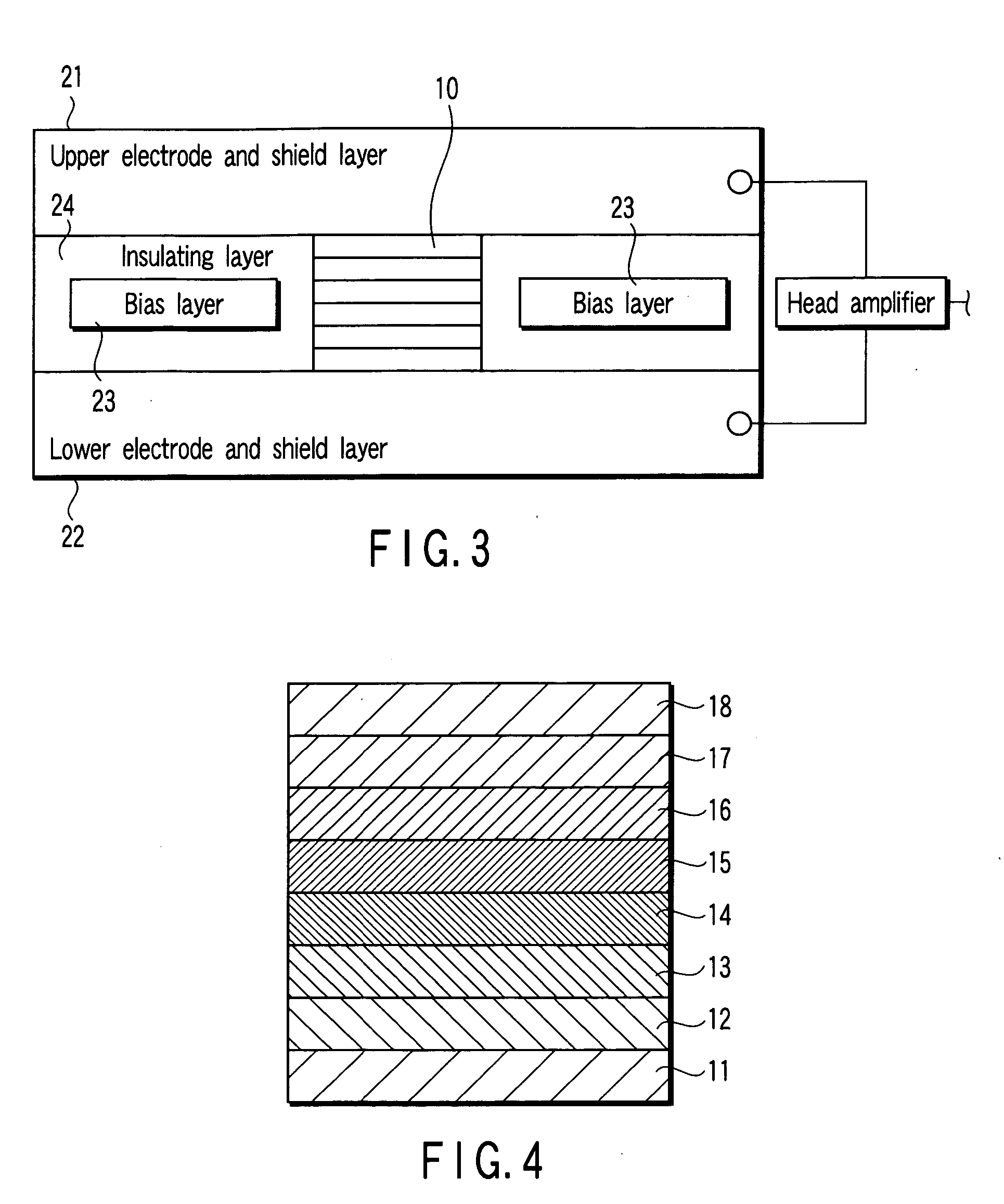
[0041]FIG. 7 schematically shows an exemplary magnetoresistive effect film 10 in a third embodiment of a magnetic disk apparatus according to the present invention. In the third embodiment, the configuration of the nonmagnetic intermediate layer 17 in the magnetoresistive effect film 10 of FIG. 4 is changed. Specifically, instead of the uniform composition, the nonmagnetic intermediate layer (indicated by numeral 31) is so configured that a conductive material 34 lies scattered in an insulating material 33 as shown in FIG. 7. The insulating material 33 insulates adjacent layers (the magnetization fixing layer 14 and magnetization free layer 16 of FIG. 4) from one another electrically. The conductive material 34, which is formed dispersively in the insulating material 33, connects the magnetization fixing layer 14 and magnetization free layer 16 electrically. This causes sense current to pass through the conductive material in a confined manner. This phenomenon is known as the curren...


PUM

PropertyMeasurementUnit
cut-off frequencyaaaaaaaaaa
sizeaaaaaaaaaa

Abstract

A magnetic disk apparatus with a magnetic disk medium capable of recording data magnetically, comprises a current perpendicular to plane magnetic reproducing head which includes a magnetoresistive effect element composed of a plurality of magnetic films stacked one on top of another and causes sense current to flow in the direction perpendicular to the stacked faces of the plurality of magnetic films, a high-pass filter which suppresses the low-frequency component of a reproduced signal output from the magnetic reproducing head, and a reproduced-signal processing section which reproduces the data from the reproduced signal which has the low-frequency component suppressed.

Description

CROSS-REFERENCE TO RELATED APPLICATIONS [0001] This application is based upon and claims the benefit of priority from Japanese Patent Application No. 2005-097720, filed Mar. 30, 2005, the entire contents of which are incorporated herein by reference. BACKGROUND [0002] 1. Field [0003] One embodiment of the invention relates to a magnetic disk apparatus using a current perpendicular to plane (CPP) magnetic head. [0004] 2. Description of the Related Art [0005] In recent years, the size of a magnetic recording apparatus, such as a hard disk unit, has been getting increasingly smaller and the recording density has been getting higher. This trend is expected to get stronger in future. As the recording density is getting higher, a higher-sensitivity sensor is required. To meet this requirement, a CPP-GMR (current perpendicular to plane—GMR) element has been developed. Using CPP-GMR elements makes it possible to form a high-density, high-output magnetic head. [0006] In a magnetic head using...

Claims


Application Information

Patent Timeline
Patent Type & Authority Applications(United States)
IPC IPC(8): G11B5/03
CPCB82Y10/00B82Y25/00G11B2005/3996G11B2005/0016G11B5/3929
Inventor FUNAYAMA, TOMOMI
Owner KK TOSHIBA
Why Eureka
Try Eureka