
Magnetic head and manufacturing method of the same

a manufacturing method and head technology, applied in the direction of maintaining the head carrier alignment, recording information storage, instruments, etc., can solve the problems of unstable floating property, unstable floating property, and head crash, so as to prevent degradation of the lubricating layer, high quality, and uneven film thickness generation

Inactive Publication Date: 2006-10-05
FUJITSU LTD
View PDF5 Cites 10 Cited by
  • Summary
  • Abstract
  • Description
  • Claims
  • Application Information

AI Technical Summary

Benefits of technology

[0010] Another and more specific object of the present invention is to provide a magnetic head having good floating stability and a manufacturing method of the same.
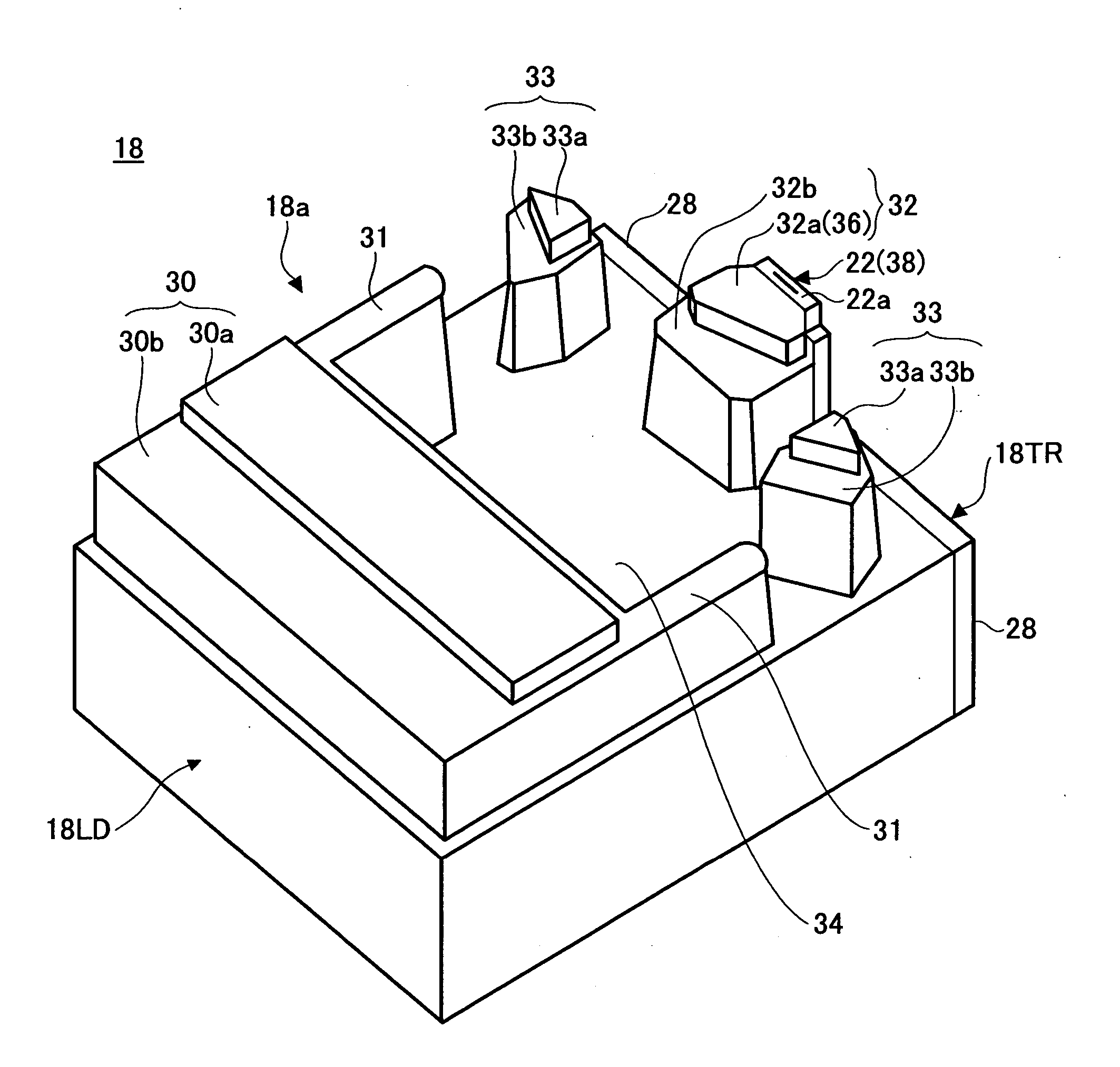
[0017] In addition, since the first air bearing surface has the average surface roughness larger than an average surface roughness of the surface of the element part, it is possible to reduce the Van der Waals force with the recording medium surface. In addition, since the first air bearing surface has a large average surface roughness, the surface free energy of the first air bearing surface is low. Therefore, the surface free energy and the Van der Waals force of the first air bearing surface can be reduced due to the lubricating layer and a rough surface. As a result of this, even if the first air bearing surface and the recording medium come too close at the time of floating, the attraction force working between the first air bearing surface and the recording medium can be reduced so that adhesion can be prevented. Hence, it is possible to realize a magnetic head having good floating stability.
[0019] Since the adsorption prevention pad comes close to the recording medium surface at the time of floating of the head slider, the lubricating layer is formed on the surface of the adsorption prevention pad and the magnetic head having good floating stability can be realized by making the average surface roughness large.
[0021] The average surface roughness of the air bearing surface of the conventional magnetic head is approximately 0.2 nm. The first air bearing surface of the present invention is set to be rougher than the conventional air bearing surface. The above-mentioned range is obtained by the following embodiment. If the average surface roughness is smaller than 0.4 nm, the attraction force working between the air bearing surface and the recording medium is dramatically increased. If the average surface roughness is larger than 3.0 nm, the probability of contact with the recording medium at the time of floating is increased.
[0027] According to this invention, in this manufacturing method, the lubricating layer is formed after the medium facing surface is formed. Hence, it is possible to avoid giving the bad influence to the lubricating layer at the time of processing the medium facing surface such as a reactive ion etching processing or elimination of a photo resist film, and thereby the generation of unevenness of the film thickness of the lubricating layer and degradation of the lubricating layer can be prevented. Therefore, a uniform lubricating layer having a high quality can be formed on a rough air bearing surface, so that a magnetic head having good floating stability can be formed.

Problems solved by technology

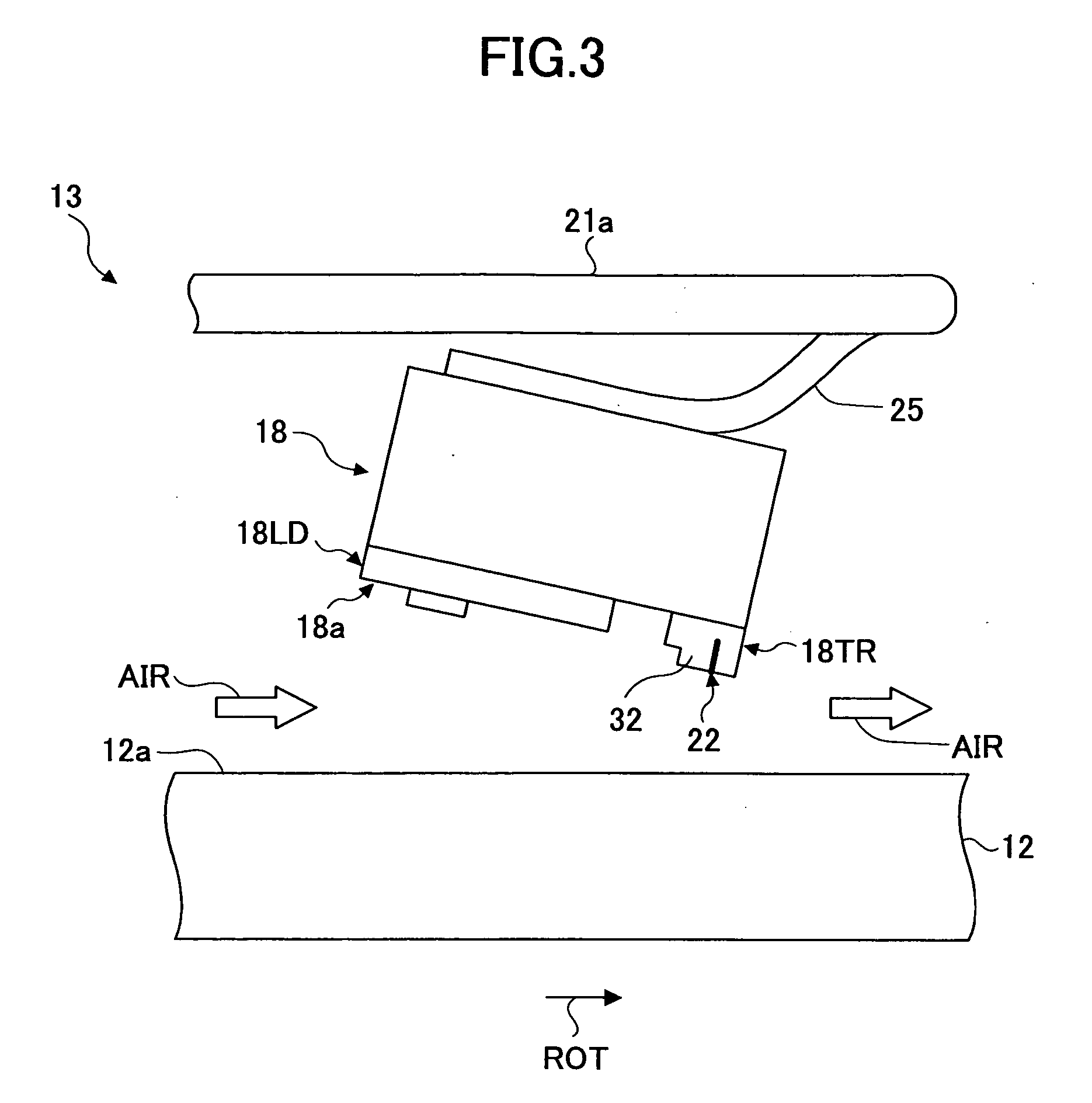
Accompanying the high recoding density of the magnetic storage apparatus, the floating amount of the magnetic head is reduced to be approximately ten and several nm and therefore a floating property may be unstable for various reasons.
Furthermore, an error occurs due to unstableness of a recording reproducing property and a head crash may be generated due to contact between the head slider of the magnetic head and the magnetic disk.
Volatile organic matter or dust inside the magnetic storage apparatus is adsorbed to the medium facing surface of the head slider or a surface of the magnetic disk so that the floating property is made unstable.
Meanwhile, as the distance between the medium facing surface of the head slider and the magnetic disk surface is shortened, Van der Waals force works between the medium facing surface and the magnetic disk as an attraction force having an un-ignorable large amount, so that a bad influence is given to the floating stability.
If an area of a rear rail is reduced to reduce the Van der Waals force, the floating amount is reduced so that it is difficult to make a floating design and the volatile organic matter or the dust inside of the magnetic storage apparatus is further adsorbed to the medium facing surface of the head slider or the surface of the magnetic disk so that the floating property is made further unstable.
In a case where the lubricating layer is simply formed on the medium facing surface in the magnetic head whose floating amount is extremely small as shown in Japan Patent Application Publication No. 5-325161, the Van der Waals force cannot be ignored and the floating stability may not be sufficient.

Method used


Image

  • Magnetic head and manufacturing method of the same
  • Magnetic head and manufacturing method of the same
  • Magnetic head and manufacturing method of the same

Examples


Embodiment Construction

[0042] A description is given below, with reference to the FIG. 1 through FIG. 13 of embodiments of the present invention.

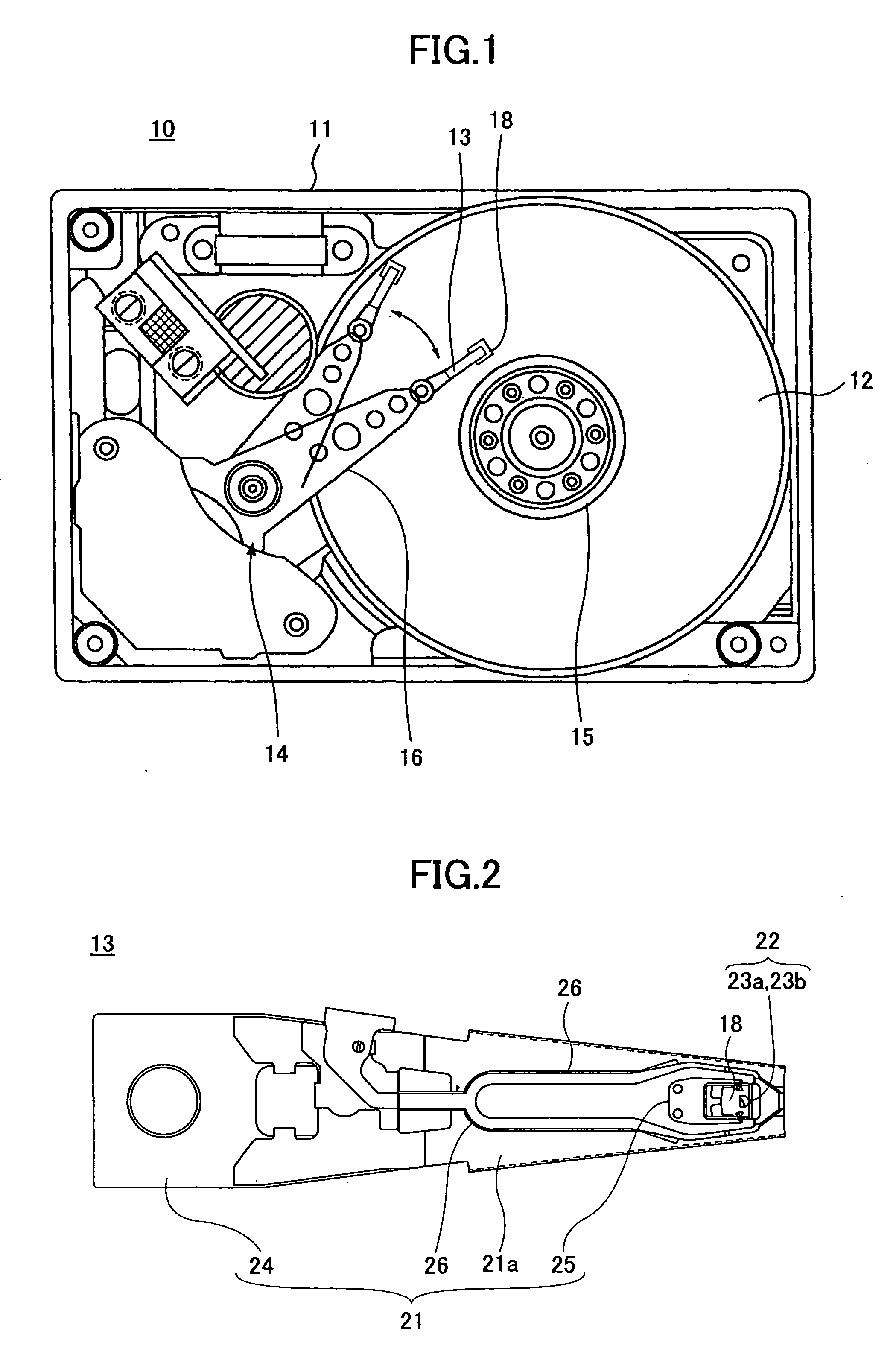
[0043]FIG. 1 is a plan view showing a main part of a magnetic storage apparatus of the embodiment of the present invention.

[0044] Referring to FIG. 1, a magnetic storage apparatus 10 has a structure where a magnetic disk 12, a magnetic head 13, an actuator unit 14, or the like are stored in a housing 11. The magnetic disk 12 fixed to a hub 15 is driven by a spindle motor (not shown). A base part of the magnetic head 13 is fixed to an arm 16 so that the magnetic head 13 is installed in the actuator unit 14 via the arm 16. The magnetic head 13 is rotated in a direction of the diameter of the magnetic disk 12 by the actuator unit 14. An electronic substrate (not shown) provided at a back side of the housing 11 performs recording reproduction control, magnetic head position control, spindle motor control, and others.

[0045] An in-plane magnetic recording medium, a ...


PUM

PropertyMeasurementUnit
surface roughnessaaaaaaaaaa
thicknessaaaaaaaaaa

Abstract

A magnetic head includes a head slider configured to float above a recording medium and having an element part for recording to and reproducing from the recording medium, the element part being situated on a medium facing surface facing to the recording medium. The medium facing surface has a first air bearing surface situated in a vicinity of a side of an air flow-out end. The medium facing surface has a rear rail having the element part situated at the side of the air flow-out end of the first air bearing surface. The first air bearing surface is covered with a lubricating layer made of water repellent resin and has an average surface roughness larger than an average surface roughness of a surface of the element part.

Description

BACKGROUND OF THE INVENTION [0001] 1. Field of the Invention [0002] The present invention generally relates to magnetic heads and manufacturing methods of the same, and more specifically, to a magnetic head having good floating stability in a case of a low floating amount and a manufacturing method of the same. [0003] 2. Description of the Related Art [0004] In a magnetic storage apparatus having a magnetic disk, a magnetic head records information on the magnetic disk or reproduces information recorded on the magnetic disk while a constant distance between the magnetic disk and the magnetic head is kept. Recently and continuing, accompanying improvement in recording density of the magnetic disk, the distance between the magnetic head and the magnetic disk, that is a floating amount, is being reduced. This is because the information recorded on the magnetic disk is made minute and therefore it is necessary to make the magnetic head come close to the magnetic disk and apply a recordi...

Claims


Application Information

Patent Timeline
Patent Type & Authority Applications(United States)
IPC IPC(8): G11B5/60
CPCG11B5/6005G11B5/6082
Inventor WATANABE, JUNKASAMATSU, YOSHIHARUMUSASHI, TAKAYUKICHIBA, HIROSHI
Owner FUJITSU LTD
Learn More