Light source module, backlight unit, and liquid crystal display device

a light source module and backlight technology, applied in the field of backlight units and/or light source modules, can solve the problems of significant weakening of green and red wavelengths, low color reproducibility via color filters, so as to improve color reproducibility and simplify circuits , the effect of reducing the size of the light source modul

Inactive Publication Date: 2006-10-05
SHARP KK
View PDF6 Cites 36 Cited by
  • Summary
  • Abstract
  • Description
  • Claims
  • Application Information

AI Technical Summary

Benefits of technology

[0008] In order to solve the foregoing object, a light source module of the present invention is a light source module for use in a backlight unit of a display device, including a luminous element for emitting light having at least two peak wavelengths. In the configuration, a light of two colors (e.g. blue and green) is produced with the use of the single luminous element. By mixing the two colors, white light is obtained. In this configuration, a circuit for driving (causing light emission fro

Problems solved by technology

However, in the method using a luminescence material, the wavelengths of the green and red are significantly weakened.
This, along with an unevenness in application of the luminescence material, causes significantly low color reproducibility via a color filter.
Further, the method of using a plurality of monochromatic LEDs have the following problems.
However, the absence of a red-color causes a low color reprod

Method used


Image

  • Light source module, backlight unit, and liquid crystal display device
  • Light source module, backlight unit, and liquid crystal display device
  • Light source module, backlight unit, and liquid crystal display device

Examples


Embodiment Construction

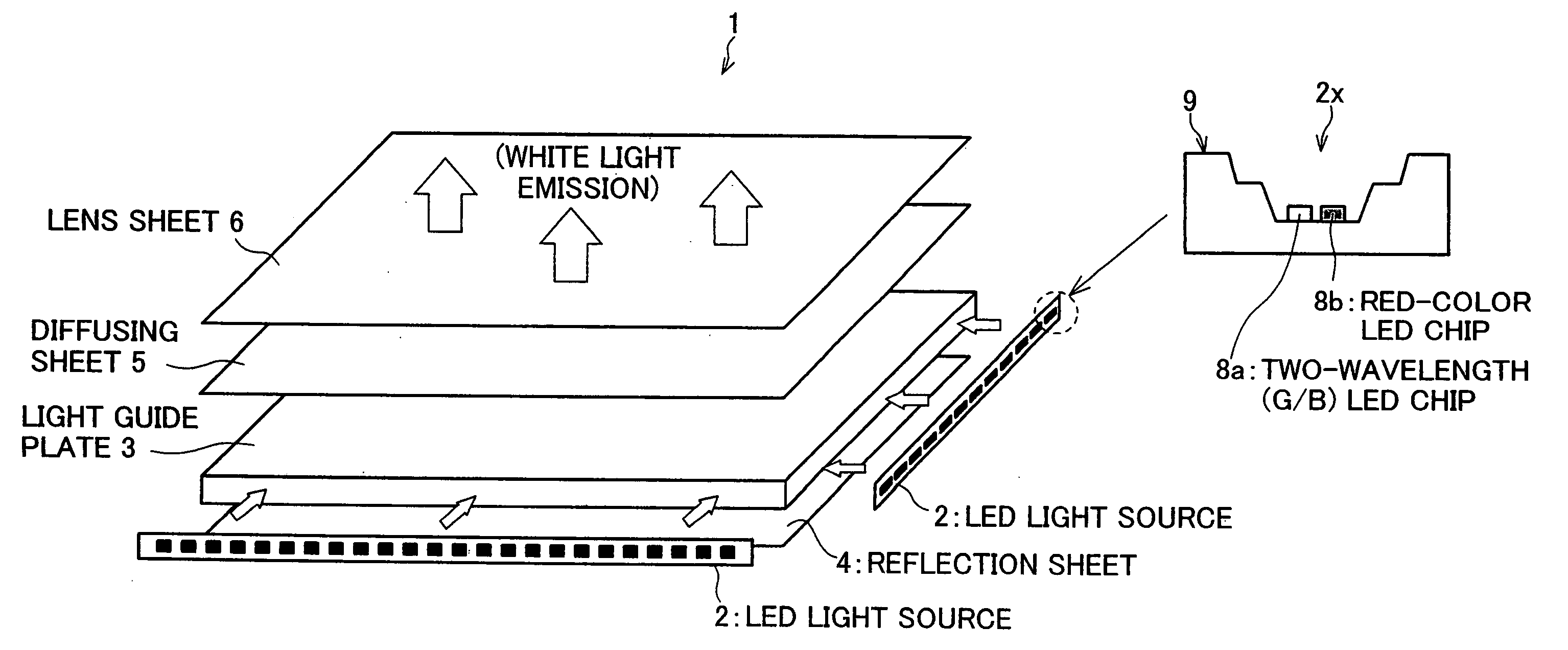
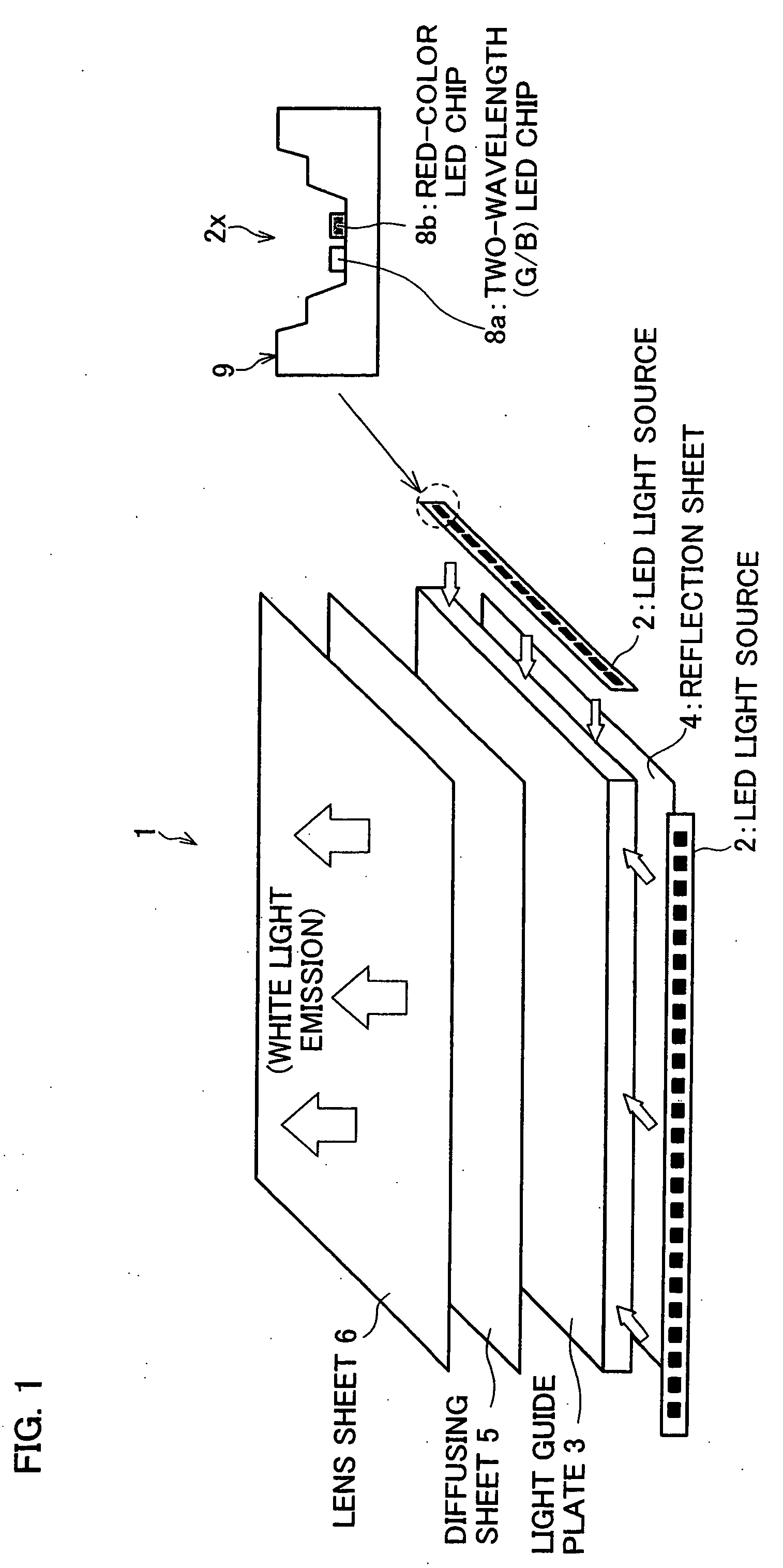
[0020] The following describes, with reference to FIG. 1 to FIG. 9, an embodiment of the present invention. FIG. 1 is an exploded perspective view illustrating a configuration of a backlight unit (for use in an instrumental panel of an automobile), in accordance with the present invention. As illustrated in the figure, the backlight unit 1 includes: an LED (light-emitting diode) light source 2 (light source module), a reflection sheet 4, a light guide plate 3, a diffusing sheet 5 and a lens sheet 6. Further, the LED light source 2 includes: at least one module substrate 9, at least one two-wavelength LED chip 8a, at least one red color LED chip 8b; and a light source control circuit (not shown).

[0021] The LED light source 2 is placed along a plane-directional edge of the flat light guide plate 3. In the backlight unit 1, the reflection sheet 4, the light guide plate 3, the diffusing sheet 5, and the lens sheet 6 are laminated in this order. Further, a display panel (not shown) incl...


PUM


Abstract

A light source module of the present invention includes: a first luminous element for emitting light having two peak wavelengths; and a second luminous element for emitting light having a single peak wavelength. With this configuration, it is possible to downsize the light source module, and improve a color reproducibility via a color filter.

Description

[0001] This Nonprovisional application claims priority under 35 U.S.C. § 119(a) on Patent Application No. 2005 / 104900 filed in Japan on Mar. 31, 2005, the entire contents of which are hereby incorporated by reference. FIELD OF THE INVENTION [0002] The present invention relates to a backlight unit and / or a light source module for use in a liquid crystal display device or the like. BACKGROUND OF THE INVENTION [0003] A study has been conducted for developing a method of utilizing an LED (Light Emitting Diode) for manufacturing a white light source used in a backlight unit. As an example of such a method, the following methods are known. Namely, one of them is a method using a luminescence material, and another is a method in which a plurality of monochromatic LEDs are used. As illustrated in FIG. 10, in the former method in which the luminescent material is used, a luminescent material is used for producing white light, by converting radiated light from an LED (B chip) of ultraviolet t...

Claims


Application Information

Patent Timeline
IPC IPC(8): F21V7/04H01L33/08
CPCG02F1/133609H01L25/0753H05B33/0818H05B33/0821H01L2224/48465H05B33/0857H01L2224/48091H01L2924/00014H05B45/20H05B45/37H05B45/42
Inventor CHIKUGAWA, HIROSHIKATOH, MASAAKIITO, MASAYUKIINOGUCHI, TSUKASA
Owner SHARP KK
Why Eureka
Try Eureka