Optical switch apparatus and control information updating method therein

a technology of optical switch and control information, which is applied in the direction of electrical apparatus, instruments, optics, etc., can solve the problems of difficulty in executing the control to make the output power value constant, affecting the error-free reception in the optical receiver, and interfere with the error-free reception

Inactive Publication Date: 2006-10-05
FUJITSU LTD
View PDF7 Cites 15 Cited by
  • Summary
  • Abstract
  • Description
  • Claims
  • Application Information

AI Technical Summary

Benefits of technology

[0048] Yet moreover, of the input side deflecting units, the input side deflecting unit disposed to deflect signal light from an input port closer to an end position has more optical deflecting elements each showing a deflection characteristic in a direction opposite to the end position, and of the output side deflecting units, the output side deflecting unit corresponding to an output p...

Problems solved by technology

At this time, different output power values appear among frame signal lights to be outputted due to difference in input power, difference in loss between optical switch ports, or the like, which affects the error-free reception in an optical receiver.
However, a concrete control mode of varying the intensity of an inputted light is not disclosed by this optical deflector.
Although the patent documents 3 to 6 disclose a variable optical attenuator for feedbacking an attenuation quantity (value) of an outputted light for carrying out variable control, through such feedback control, difficulty is experienced in executing the control to make the output power value constant with respect to a frame signal light undergoing the switching processing in a time dimension shorter than...

Method used


Image

  • Optical switch apparatus and control information updating method therein
  • Optical switch apparatus and control information updating method therein
  • Optical switch apparatus and control information updating method therein

Examples


Embodiment Construction

[0065] Embodiments of the present invention will be described hereinbelow with reference to the drawings.

[0066] In addition to the objects of the present invention, other technical objects, means for achieving the technical objects and the effects thereof will become apparent from the disclosure of the following embodiments.

[0067] [A] Description of Embodiment

[0068] [A1] Total Configuration

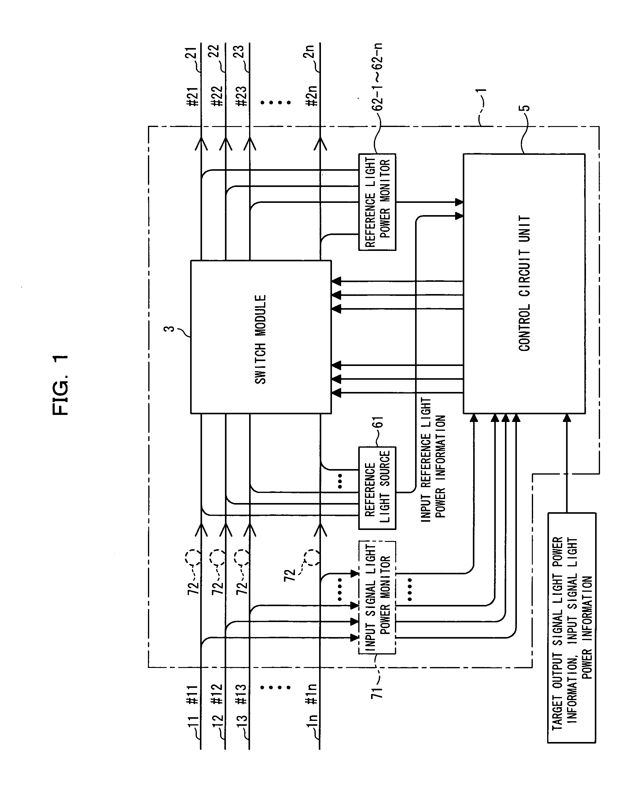
[0069]FIG. 1 is an illustration of an optical switch apparatus 1 according to an embodiment of the present invention. The optical switch apparatus 1 shown in FIG. 1 is made to switching-setting a route between one of a plurality of (n) input side optical fibers 11 to 1n and one of a plurality of (n) output side optical fibers 21 to 2n, and it comprises a switch module 3 and a control circuit unit 5 for controlling the switch module 3.

[0070] In this configuration, the switch module 3 receives signal lights from the n input side optical fibers 11 to 1n through input ports #11 to #1n of the opti...


PUM


Abstract

The present invention relates to an optical switch apparatus made to successively carry out the route switching with respect to frame signal light inputted through various paths while eliminating the dispersion of an output power value. In the optical switch apparatus, input side deflecting units are disposed in corresponding relation to a plurality of input ports and output side deflecting units are disposed in corresponding relation to a plurality of output ports. Each input side deflecting unit and each output side deflecting unit are constructed in a manner such that a plurality of optical deflecting elements made to deflect signal light in response to an electric field applied are arranged in a cascade fashion, and the optical deflecting element constituting the input side deflecting unit or the output side deflecting unit is made so as to variably adjust the level of signal light to be outputted from the output side deflecting unit to the output port.

Description

BACKGROUND OF THE INVENTION [0001] 1) Field of the Invention [0002] The present invention relates to an optical switch apparatus and a control information updating method therein, which are suitable for use in the construction of an optical communication system in which a large capacity of information modulated into an optical signal is handleable as an optical signal without being converted into an electric signal, and more particularly to an optical switch apparatus and a control information updating method therein suitable for use in a network which is made to conduct optical burst signal processing. [0003] 2) Description of the Related Art [0004] In the case of a photonic network in a metro access area, a network configuration is frequently changed through the exchange / route-switching of a line or signal at ADM (Add Drop Multiplexing) . At a repeating stage or the like in the current network, in large quantities there have been employed configurations which are designed to carry...

Claims


Application Information

Patent Timeline
IPC IPC(8): G02B6/35
CPCH04Q2011/0049H04Q11/0005
Inventor TAKITA, YUTAKAKAI, YUTAKA
Owner FUJITSU LTD
Why Eureka
Try Eureka