Optical recording medium

a technology of optical recording medium and optical disc, which is applied in the direction of data recording, record carrier materials, instruments, etc., can solve the problems of disc warpage, disc warpage, and disc warpage, so as to prevent the effect of moisture absorption/releas

Inactive Publication Date: 2006-10-05
TDK CORPARATION
View PDF6 Cites 20 Cited by
  • Summary
  • Abstract
  • Description
  • Claims
  • Application Information

AI Technical Summary

Benefits of technology

[0024] (6) The optical recording medium according to (5), further comprising a warpage preventing layer provided between the moisture proof layer and the label printing layer, for keeping moisture absorption to and releasing from the light transmitting layer in balance.
[0025] According to the invention, a moisture proof layer is provided on the warpage adjusting layer prone to have warpage caused by moisture absorption / releasing, and therefore the warpage caused by moisture absorption / releasing can be prevented.

Problems solved by technology

As a result, abrupt vibrations in a recording and reproducing apparatus or the warpage or surface sway of the disc could cause the pickup head and the optical disc to contact with each other.
Therefore, the disc is more likely to suffer from warpage caused by environmental changes (in temperature and humidity).
The generated warpage could deform the optical disc, which causes the optical disc and the pickup head to collide with each other, and the recording or reproducing could probably be adversely affected.
In this case, the light transmitting layer is composed of a UV curable resin coated by spin coating, and therefore the optical disc suffers from warpage caused by shrinkage on curing.
However, when the hard resin spacer layer is provided between the recording layers, the optical recording medium greatly warps.
However, the warpage adjusting layer has an expansion / shrink property as it absorbs or releases moisture, and therefore the layer expands / shrinks with environmental changes, which causes the optical disc to warp.

Method used


Image

  • Optical recording medium
  • Optical recording medium
  • Optical recording medium

Examples


examples

[0087] Now, an example of an optical recording medium produced in the same manner as the exemplary embodiments of the invention will be described.

[0088] A polycarbonate substrate having a thickness of 1.1 mm and an outer diameter of 120 mm was produced by injection molding. There were pits and grooves on the substrate.

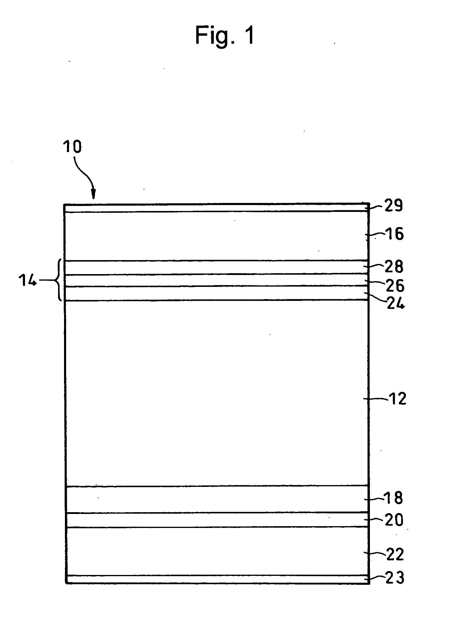
[0089] A first information layer was deposited on the surface of the polycarbonate substrate by sputtering. More specifically, a reflection layer having a thickness of approximately 100 nm and composed of a material containing Al, Pd, and Cu in a mixing ratio of 98 (Al): 1(Pd): 1(Cu), a dielectric layer having a thickness of approximately 40 nm and composed of a material containing ZnS (zinc sulfide) and SiO2 (silicon dioxide) in a mixing ratio of 80 (ZnS): 20(SiO2), an alloy layer having a thickness of approximately 5 nm and composed of a material containing Cu, Al, and Au in a mixing ratio of 64 (Cu): 23(Al): 23(Au), a protective layer having a thickness of approxi...


PUM

PropertyMeasurementUnit
glass transition point Tgaaaaaaaaaa
distanceaaaaaaaaaa

Abstract

An optical recording medium includes a recording layer provided on a substrate. The recording layer includes first and second information layers and a spacer layer therebetween. The optical recording medium also includes a warpage adjusting layer provided on the side of the substrate opposite to the recording layer to reduce the warpage of the spacer layer caused by curing. A moisture proof layer is formed on the surface of the warpage adjusting layer opposite to the recording layer to reduce the warpage of the warpage adjusting layer caused by moisture absorption and releasing by the warpage adjusting layer.

Description

BACKGROUND OF THE INVENTION [0001] 1. Field of the Invention [0002] The present invention relates to an optical recording medium that has a stable warpage amount regardless of environmental changes. [0003] 2. Description of the Related Art [0004] Optical discs suitable for the system using the blue laser light technology has been developed as optical recording media having a storage capacity larger than that of a DVD (Digital Versatile Disc). [0005] In such an optical disc, the recording reproducing wavelength λ is set to 405 nm and the objective lens numerical aperture NA of the pickup head is raised to 0.85, so that the storage capacity can be as large as 25 GB. However, with the large NA value, the distance between the objective lens and the optical disc is as short as approximately 150 μm. [0006] As a result, abrupt vibrations in a recording and reproducing apparatus or the warpage or surface sway of the disc could cause the pickup head and the optical disc to contact with each ...

Claims


Application Information

Patent Timeline
Patent Type & Authority Applications(United States)
IPC IPC(8): B32B3/02G11B7/24G11B7/2403G11B7/24038G11B7/24056G11B7/24067G11B7/24094G11B7/24097G11B7/254G11B7/257
CPCG11B7/2403G11B7/252G11B7/246G11B7/24038
Inventor YAMADA, TAKASHIKOMAKI, TSUYOSHIYAMAGA, KENJI
Owner TDK CORPARATION
Why Eureka
Try Eureka