
Control system for adjustable damping force damper

a control system and damper technology, applied in position/direction control, position/direction control, registration/indication of vehicle working, etc., can solve the problem of peculiar feeling of the driver, and achieve the effect of good precision and without deterioration of high responsibility

Active Publication Date: 2006-10-05
HONDA MOTOR CO LTD
View PDF19 Cites 58 Cited by
  • Summary
  • Abstract
  • Description
  • Claims
  • Application Information

AI Technical Summary

Benefits of technology

[0008] The present invention has been made to deal with such afore-described disadvantages, and it is one of objects of the present invention to provide a control system for an adjustable damping force damper, which is improved to get the proper roll stiffness at a time of turning without a deterioration of a high responsibility; and also, to make it possible to set a target damping force of a damper with good precision by sensing exactly a lateral acceleration at a position of a suspension apparatus.
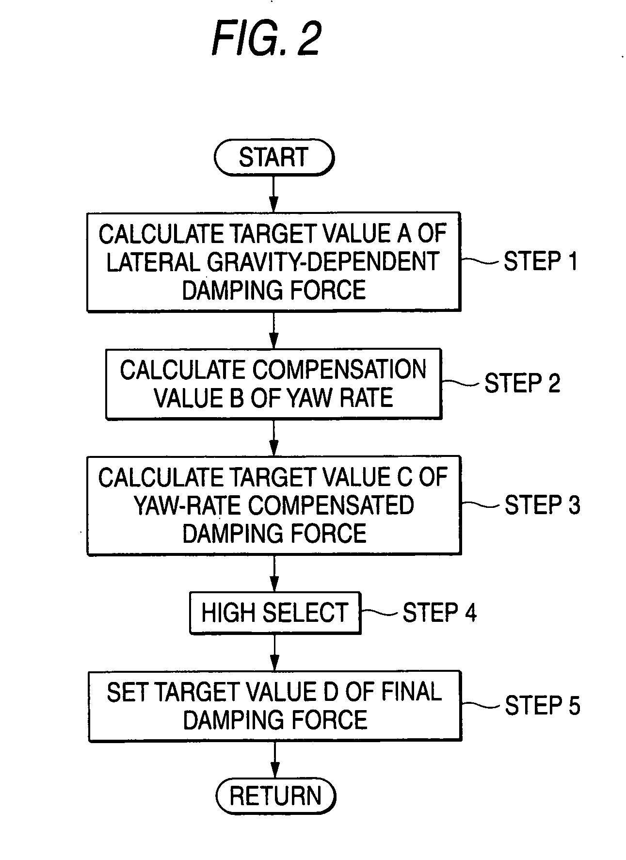
[0036] According to the present invention, for example, a value having a larger absolute value is selected from the target value A of the damping force control, which is derived by multiplying a derivative value of the lateral acceleration by a predetermined coefficient, and the target value C to which a phase compensation is applied by the yaw rate, and then a value to which a sign of the target value having a higher absolute value out of them is affixed is set as the final target value D in control. As a result, a driver's stepped feeling in the damping force control can be eliminated while maintaining a high responsibility.
[0037] According to the above configuration, the lateral acceleration at the position of the suspension apparatus (S) is calculated by taking account of not only the lateral acceleration generated by a turning of the vehicle but also the lateral acceleration generated by a yawing of the vehicle. Therefore, the damping force to be generated in the damper based on this lateral acceleration can be decided exactly, and particularly the driving stability performance in a low speed range can be enhanced.

Problems solved by technology

As a result, it is possible that such situation leads the driver to feel a peculiar feeling as if the damper breaks down unexpectedly for an instant.

Method used


Image

  • Control system for adjustable damping force damper
  • Control system for adjustable damping force damper
  • Control system for adjustable damping force damper

Examples


Embodiment Construction

[0050] The present invention will be explained in detail with reference to the accompanying drawings hereinafter.

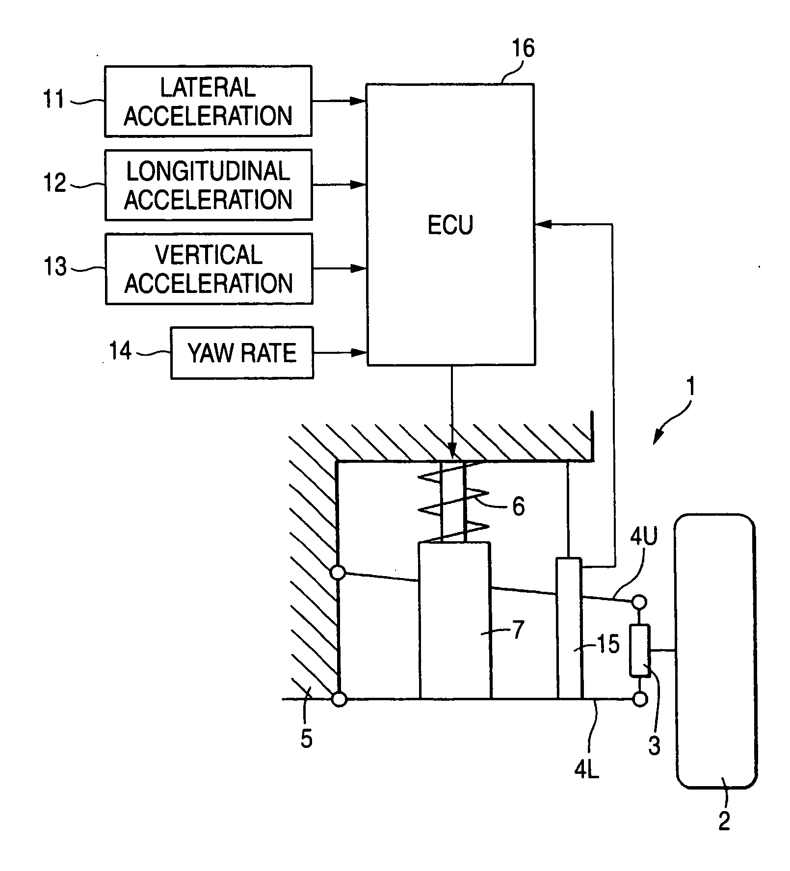
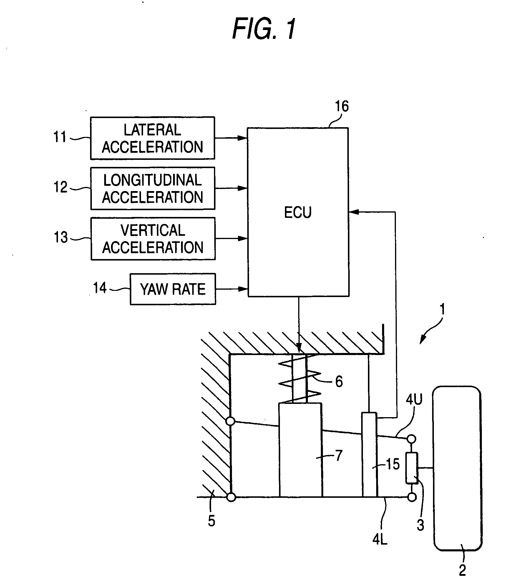
[0051]FIG. 1 shows an example of a basic configuration of a car suspension apparatus that supports a car body on front / rear and left / right wheels of a four-wheel car. This suspension apparatus 1 includes a knuckle 3 for supporting a tire 2, upper and lower suspension arms 4U, 4L for supporting vertically movably the knuckle 3 onto a car body 5, and a compression coil spring 6 and a hydraulic damper 7 provided in parallel between the lower suspension arm 4L and the car body 5.

[0052] As the hydraulic damper 7, an adjustable damping force damper into which MRF (Magneto-Rheological Fluid), for example, is sealed is employed. In this damper 7, when a piston is moved vertically and the damper is contracted / expanded, the MRF flows between a piston upper chamber and a piston lower chamber via orifices provided in the piston, and an apparent viscosity of the MRF is changed by co...


PUM


Abstract

A control system for an adjustable damping force damper of a suspension apparatus of a vehicle, includes a lateral acceleration detecting unit detecting a lateral acceleration of the vehicle at a gravity point thereof, a yaw rate detecting unit detecting a yaw rate of the vehicle and a control unit controlling a damping force of the damper. The control unit calculates a first target damping force based on an output of the lateral acceleration detecting unit, calculates a second target damping force based on a lateral acceleration at an axel position which is estimated by an output of the yaw rate detecting unit, compares an absolute value of the first target damping force with that of the second target damping force and sets a target controlling value of the damping force in accordance with the first or second target damping force which has a larger absolute value.

Description

[0001] The present invention claims foreign priority to Japanese patent applications Nos. P.2005-101580, filed on Mar. 31, 2005 and P.2005-352952, filed on Dec. 7, 2005, the contents of which are incorporated herein by reference. BACKGROUND OF THE INVENTION [0002] 1. Field of the Invention [0003] The present invention relates to a control system for an adjustable damping force damper and, more particularly, a control system for an adjustable damping force damper for controlling a rolling motion of a car body at a time of turning. [0004] 2. Description of the Background Art [0005] The spring provided to the suspension apparatus of the vehicle is deformed while absorbing a shock, and springs back in the direction to restore the deformation when an external force disappears. As a result, a reciprocating oscillation is generated. In order to attenuate an oscillation energy of this spring, a damper called the so-called shock absorber is used together in the suspension apparatus of the ve...

Claims


Application Information

Patent Timeline
Patent Type & Authority Applications(United States)
IPC IPC(8): B60G17/018
CPCB60G17/0152B60G17/08B60G2400/0523B60G2400/102B60G2400/104B60G2400/106B60G2400/202B60G2400/206B60G2400/252B60G2500/10B60G2600/184B60G2600/22
Inventor IZAWA, MASAKIKATO, TAKAFUMI
Owner HONDA MOTOR CO LTD
Learn More