Turbocharger

a technology of turbocharger and magnet, which is applied in the direction of positive displacement liquid engine, pump, machine/engine, etc., can solve the problems of magnet deformation in turbochargers, and achieve the effects of reducing vibration, improving reliability, and cooler running temperatures

Inactive Publication Date: 2006-10-12
ADVANCED PROPULSION TECH
View PDF19 Cites 52 Cited by
  • Summary
  • Abstract
  • Description
  • Claims
  • Application Information

AI Technical Summary

Benefits of technology

[0007] The present invention provides several improvements to an electrically controlled turbocharger unit that result in lower vibration, cooler running temperatures and increased reliability. Such improvements are the result of orienting the unit so that the central shaft containing the turbine and the compressor is mounted to rotate on a substantially vertical axis. This orientation results in the elimination of gravitational effects on the rotating shaft and the elements mounted thereon. In addition, an induction motor having its rotor integrally mounted on the shaft that extends between the turbine and the compressor is found to provide highly responsive characteristics and greater endurance to the high temperatures inherent in turbochargers. Further, an improved lubricating system is described to enhance the flow of lubricating fluid through the turbocharger housing and the various bearings in the unit by utilizing air pressure scavenged from the compressor and injected into upper and lower oil reservoirs.
[0008] It is an object of the present invention to provide a vertically oriented turbocharger that reduces and therefore improves the vibration characteristics of the turbo shaft at high speed rotations.
[0010] It is a further object of the invention to provide an improved lubricating system for vertically oriented turbochargers that is effective to provide lubricating fluid to the vertically spaced shaft bearings.
[0011] It is a still further object of the present invention to provide improved cooling for an electrically controlled turbocharger through the use of air scavenged from the compressor and ducted into the motor and lubricating system that circulates lubricating fluid through the housing of the turbocharger.

Problems solved by technology

Additionally, the electric motors employed in prior art turbochargers contain magnets that become degraded due to exposure to the extreme heat inherent in such applications.

Method used


Image

  • Turbocharger
  • Turbocharger
  • Turbocharger

Examples


Embodiment Construction

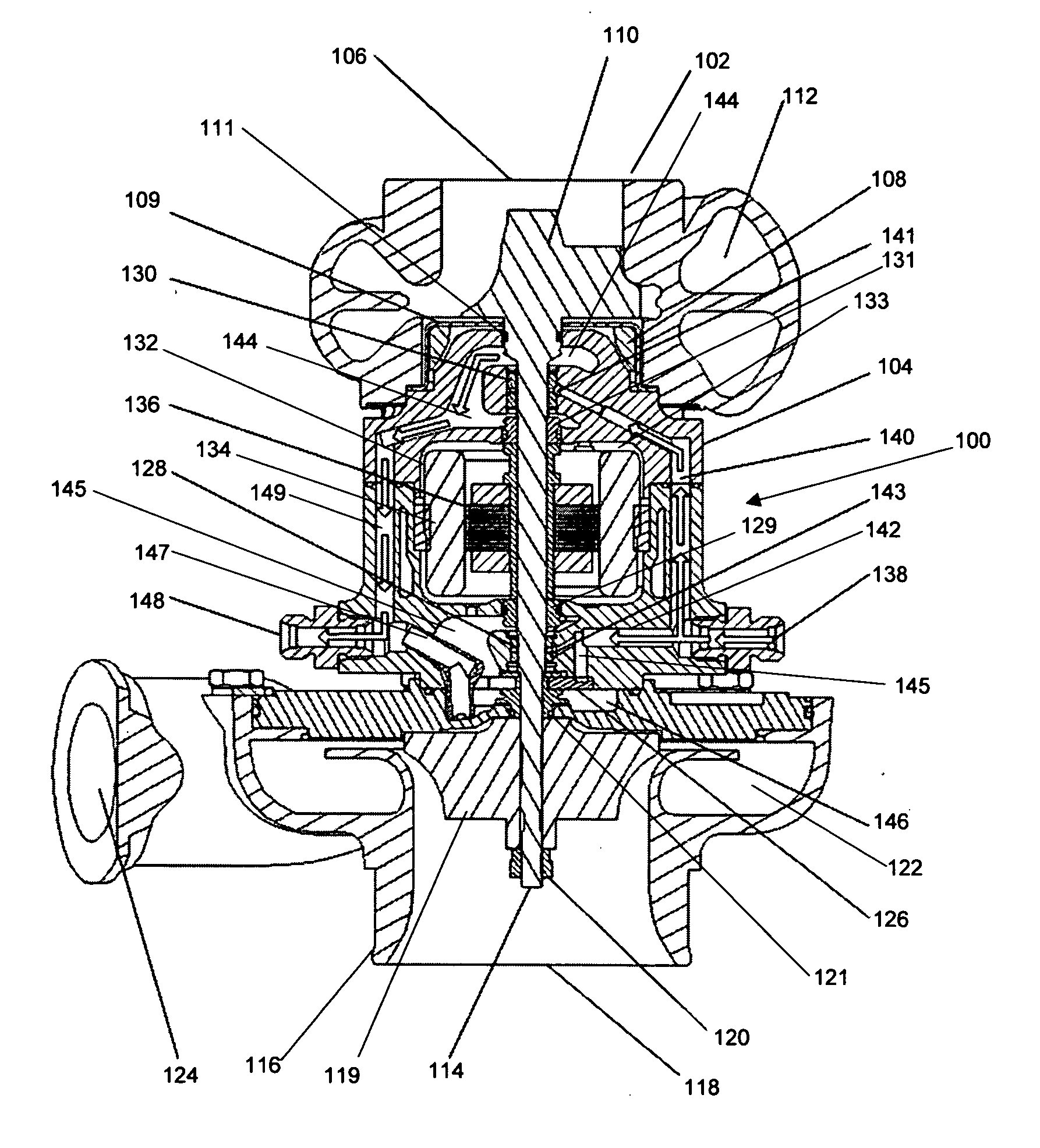
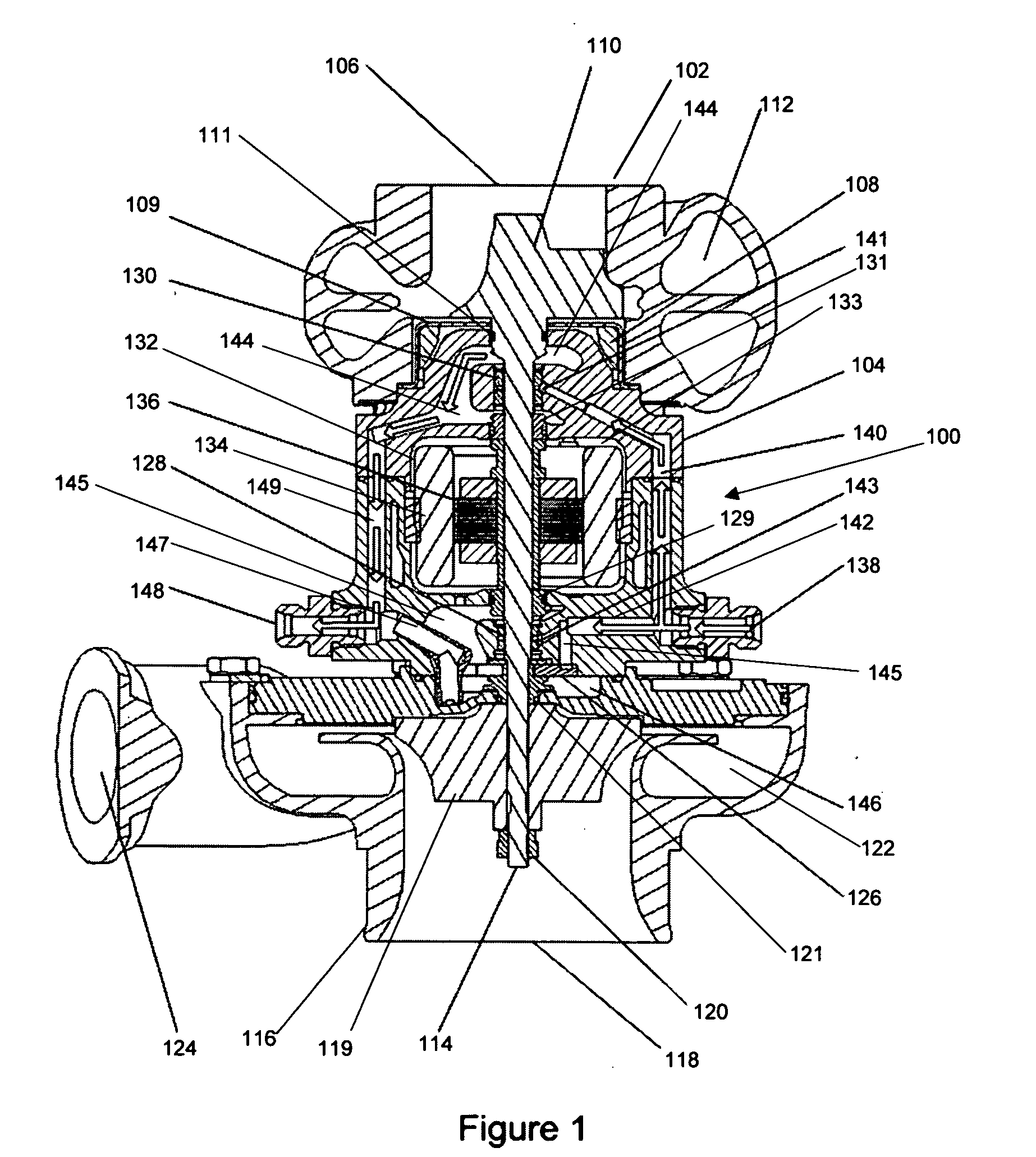
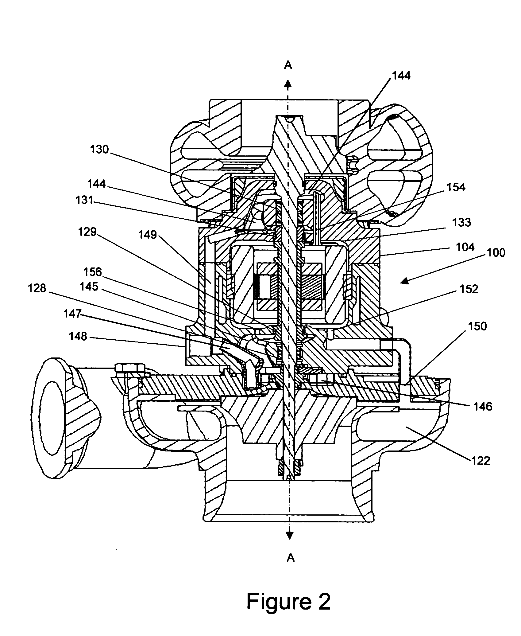
[0017] In FIG. 1, the preferred embodiment of an electrically assisted turbocharger unit 100 is depicted in a substantially vertical orientation, intended to be mounted on or in close proximity to an associated internal combustion engine.

[0018] In this embodiment, a turbine housing 102 in shown in the upper portion of FIG. 1, while a compressor housing 116 is shown in the lower portion. A motor housing 104 is shown as being intermediate the turbine and compressor housings.

[0019] A turbocharger shaft 114 is at the core of the unit and provides the mechanical drive connection between an exhaust gas turbine rotor 110 and a compressor rotor 119. In this case an induction motor 132 is provided in motor housing 104 to surround shaft 114 and a motor rotor 136 is formed to be preferably integral with shaft 114.

[0020] Turbine housing 102 provides an exhaust gas inlet port 116 that is connected to the exhaust manifold of an associated engine (not shown). Turbine housing 102 contains exhaus...


PUM


Abstract

An electrically controlled turbocharger having a substantially vertically oriented shaft interconnecting a turbine and a compressor. The vertical orientation serves to eliminate the effects of gravity on the rotating components. Placing the turbine vertically above the motor and compressor and provides additional cooling through convection of heat produced by hot exhaust gas flowing through the turbine. A lubricating system utilizes scavenged air from the compressor to draw lubricating oil through internal passages of the motor housing to maintain a desirable oil sump level, ventilate the auxiliary induction motor, and provide pressure to the oil seals of the motor cavity.

Description

RELATED APPLICATION [0001] This application and the claimed subject matter is supported by Applicant's provisional application Ser. No. 60 / 669,598 to TURBOCHARGER, filed Apr. 9, 2005 and the benefit to priority of that date is hereby claimed.BACKGROUND [0002] 1. Field of the Invention [0003] The invention relates to the field of turbochargers for use with internal combustion engines. More specifically the invention relates to specific improvements in a lubrication system for a turbocharger as well as the construction of an electrically controlled turbocharger. [0004] 2. Description of the Prior Art [0005] Turbochargers are frequently employed in association with internal combustion engines to improve engine response under varying loads. Electrically assisted turbochargers provide the added advantage of, reducing transient lag, reducing fuel consumption and lowering emission levels. Typically, an electrically assisted turbocharger employs a motor engaged to supply supplemental power ...

Claims


Application Information

Patent Timeline
Patent Type & Authority Applications(United States)
IPC IPC(8): F02B33/44
CPCF01D25/18F02B37/14F02B39/10F05D2250/315Y02T10/144F05D2220/40F02B39/14Y02T10/12
Inventor PRUSINSKI, THOMAS M.HOFBAUER, PETERSCHMIDT, JASON Z.
Owner ADVANCED PROPULSION TECH
Why Eureka
Try Eureka