
Animal deterrent apparatus for mounting to a culvert

Inactive Publication Date: 2006-10-12
ROSS BRIAN CHARLES +1
View PDF22 Cites 18 Cited by
  • Summary
  • Abstract
  • Description
  • Claims
  • Application Information

AI Technical Summary

Benefits of technology

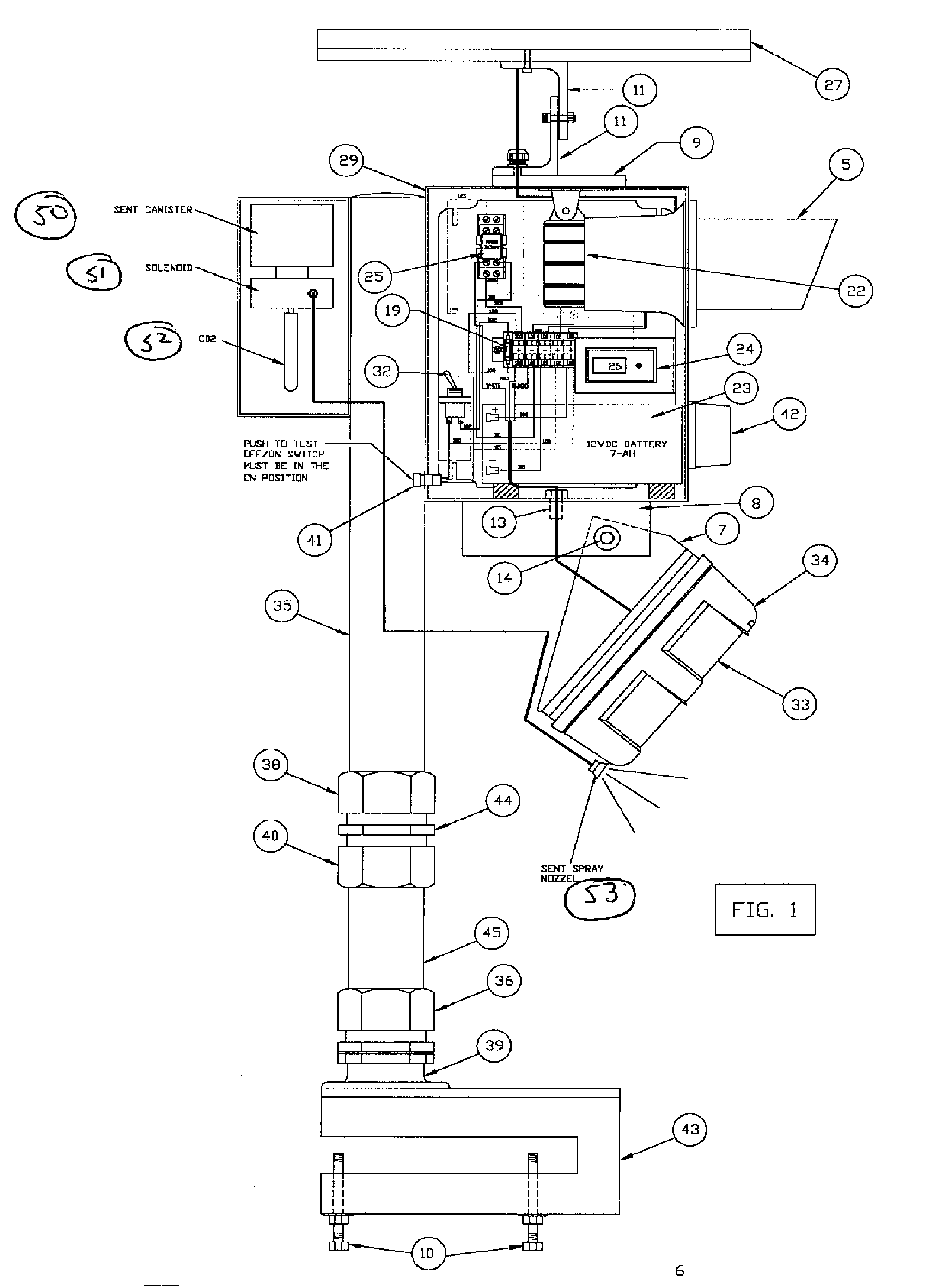
[0010] In contrast, the apparatus of the present invention is especially effective in inducing the desired animal response because its alarm activity is unmistakably related to an animal's proximity to the apparatus. To wit, the present apparatus will sit dormant and inconspicuous, unless and until its sensor component detects the body heat of an animal moving within its detection zone. Only when detection occurs will the apparatus's alarms be triggered. More specifically, upon an animal detection, the sensor component energizes a normally open 12-volt direct current relay, sending a 12-volt current to activate an audio siren, a strobe light and a scent emitter which blare loud noise, deliver rapid light flashes and spray a familiar and repelling scent, respectively. As a result, the animal is suddenly startled, as the flickering strobe light creates the illusion of a motioning object of some sort—an illusion reinforced by the fact that the siren noise and scent are projected from the same location simultaneous to the commencement of visible light flashes.
[0019] Similarly, it is yet another object of the invention to provide an animal deterrent apparatus whose alarms are triggered only by the presence of an actual pest animal. The invention uses a passive infrared heat and motion sensor that detects passive infrared radiation that is emitted by the bodies of living animals. The sensor is capable of detecting a temperature differential, between the ambient temperature and the temperature of a sensed object, as minimal as one degree Fahrenheit. In a preferred embodiment of the present invention, the sensor includes a sensitivity setting which, essentially, allows a user to calibrate the sensor to distinguish, for alarm detonation purposes, larger pest animals (such as beavers) from smaller, less problematic animals and benign objects.

Problems solved by technology

With their paddle-shaped feet and short legs, beavers are adept swimmers, but relatively slow land travelers.
Of course, where low-lying wooded land surrounds a water body, a rise in water level results in submersion of additional land and trees.
By damming around the downstream end of a culvert, the normal flow of water exiting the culvert is blocked, and the water level is raised to form a “beaver pond.” This kind of damming may be useful for the beaver, but it is quite disruptive to human life when it causes roads to flood or to develop cracks and potholes due to water saturation of the roadbed.
Clearly, beavers can present a significant financial burden to departments of transportation and other public agencies responsible for maintaining roads, and they can pose similar burdens to private landowners whose lands are flooded and whose trees are destroyed by water submersion or by beavers feeding on them.
However, many of these devices are difficult to install.
These device also require continuous maintenance, so, they often are not the most viable solutions for preventing beaver damming—particularly, around culverts.
However, because beavers often are capable of tunneling underneath exclusion devices to dam inside of them, such devices may be rendered ineffective.
However, because of the potential enormity of the beaver population around water habitats, these methods may ultimately prove futile as well.
Furthermore, in many instances, either firearms use prohibitions or animal rights considerations may dissuade one from resorting to these methods even where they potentially could be effective.
Accordingly, it stands to reason that existing animal deterrent devices, because of differences in their alarm mechanisms, are not equally effective in repelling all pest animals.
When the apparatus is triggered into action by, for example, a beaver, the beaver will be annoyed, at minimum, and is likely to perceive the generated commotion and odor as actually threatening.
Furthermore, if a once startled beaver returns to the location, the apparatus will be again triggered, and the beaver will associate that particular location to an unpleasant experience.
Furthermore, the apparatus includes its own source of power; so, proximity to an extrinsic power source is not a consideration that restricts where the deterrent apparatus can be deployed.

Method used


Image

  • Animal deterrent apparatus for mounting to a culvert
  • Animal deterrent apparatus for mounting to a culvert
  • Animal deterrent apparatus for mounting to a culvert

Examples


Embodiment Construction

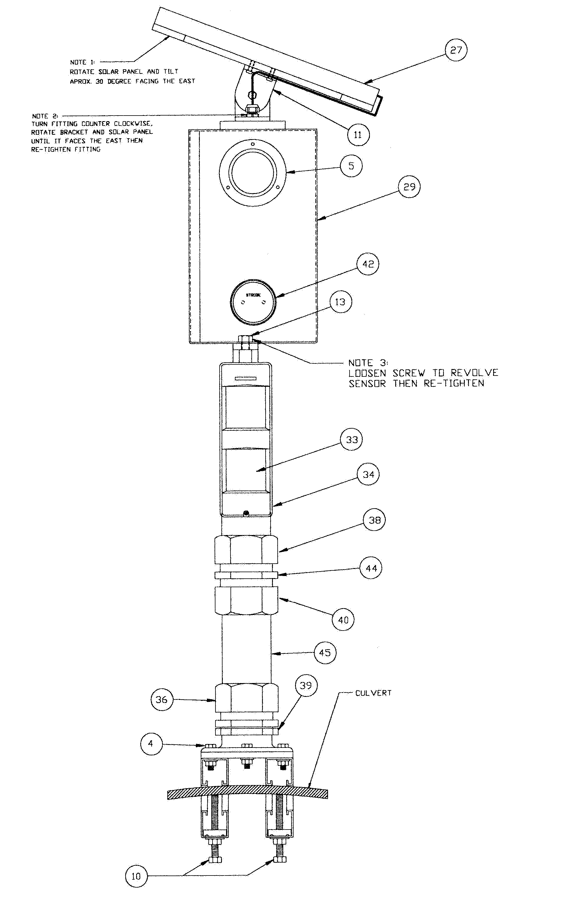
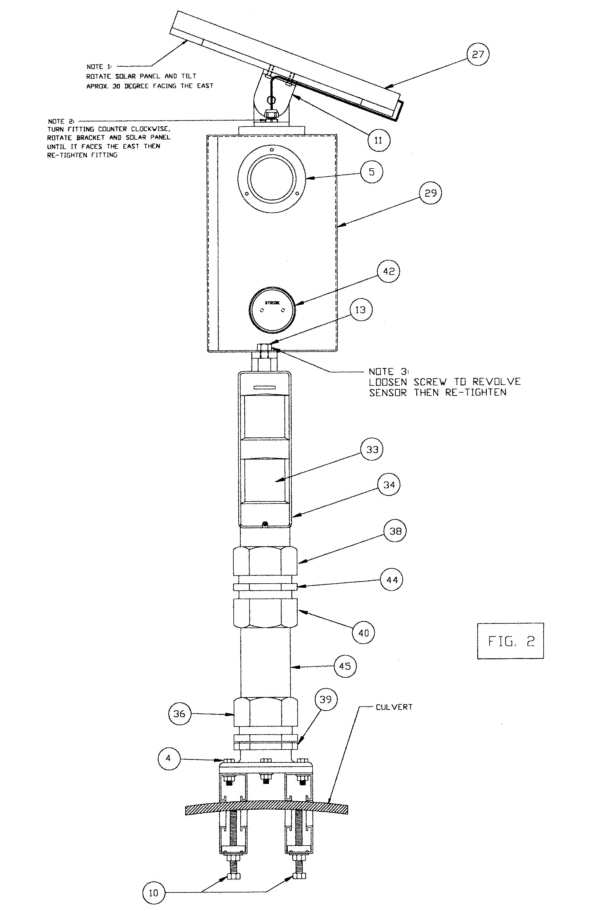
[0026] The animal deterrent apparatus of the present invention employs several integrated components. FIG. 1 is a schematic illustrating a preferred embodiment of the present invention, an embodiment whose major components include: an audio siren 22 and a strobe light 42 (together with the scent emitting parts mentioned below, referred to as “alarms”), a relay 25 and a battery 23—each of the aforementioned components disposed within a weatherproof control housing 29; a sensor 33 disposed within a weatherproof sensor housing 34; a scent reservoir 50, solenoid 51, and spray nozzle 53; a solar panel 27; and culvert mounting means comprising, primarily, a first mounting member 35, a second mounting member 45, a clamping device 43 and a clamp connecting assembly.

[0027] The control housing 29 is affixed to the first mounting member 35 at or near the proximal end of the mounting member 35. Preferably, the mounting members are metal tubes, as depicted in FIG. 1. However, mounting members, ...


PUM


Abstract

An automated animal deterrent apparatus for mounting to a culvert, the apparatus includes attached weatherproof housings to protect its other components; a passive infrared sensor to detect pest animals within a detection zone; a siren to produce noise; a scent releasing assembly to emit an odor; a strobe light to produce light flashes; a solar panel and battery to power the apparatus; and a tube and clamp assembly for attaching the apparatus to the end of a culvert.

Description

[0001] This nonprovisional application claims the benefit of provisional application 60 / 670,068BACKGROUND OF THE INVENTION [0002] The present invention generally relates to a device for deterring pest animals from the vicinity of a culvert and is specifically directed to an apparatus that is adapted for mounting to a culvert and that produces sound, scent and light for the purposes of repelling beavers and preventing them from causing the road disruption and other property damage that may result from their damming about a culvert. [0003] The beaver, North America's largest rodent, is an aquatic mammal that lives on a vegetarian diet of, mainly, leaves, sticks and tree bark. With their paddle-shaped feet and short legs, beavers are adept swimmers, but relatively slow land travelers. Consequently, beavers tend to spend most of their time either in or near bodies of water, as accessibility to swimmable water serves to minimize their vulnerabilities to land predators that are not inclin...

Claims


Application Information

Patent Timeline
IPC IPC(8): A01K15/04A01K15/02
CPCA01K15/02A01M29/10A01M31/002A01M29/16A01M29/12
Inventor ROSS, BRIAN CHARLESROSS, JAMES EDWARD
Owner ROSS BRIAN CHARLES
Learn More