Method for signal processing and a transmitting device with digital predistortion, in particular for mobile radio

a transmitting device and signal processing technology, applied in the direction of digital transmission, amplifier modification to reduce non-linear distortion, digital transmission, etc., can solve the problems of increasing the power loss of the amplifier, particularly sensitive modulation types to possible interference or distortion in the transmission path, quiescent current consumption, etc., and achieve the effect of reducing the power consumption of the transmitting devi

Inactive Publication Date: 2006-10-12
INFINEON TECH AG
View PDF14 Cites 34 Cited by
  • Summary
  • Abstract
  • Description
  • Claims
  • Application Information

AI Technical Summary

Benefits of technology

[0036] The transmitting device according to one embodiment of the invention is used to control predistortion of a modulation signal with a first and a second component as a function of a power control unit. For this purpose, the predistortion device is designed to bridge predistortion in one operating state and emit the components of the modulation signal that are applied to its input side, without distortion. In this operating state, the switching elements which are required for predistortion can be switched off, thus reducing the power consumption of the transmitting device

Problems solved by technology

The modulation types used are particularly sensitive to possible interference or distortion in the transmission path.
However, operation of the power amplifier in this way leads to a high quiescent current consumption, thus increasing the power losses in the amplifier, and thus in the transmitting device.
The increased power consumption in mobile communication appliances results in a decrease in the operating time, which is essentially predetermined by the capacity of the rechargeable batteries that are used.
In this region, the power amplifiers have a very highly non

Method used


Image

  • Method for signal processing and a transmitting device with digital predistortion, in particular for mobile radio
  • Method for signal processing and a transmitting device with digital predistortion, in particular for mobile radio
  • Method for signal processing and a transmitting device with digital predistortion, in particular for mobile radio

Examples


Embodiment Construction

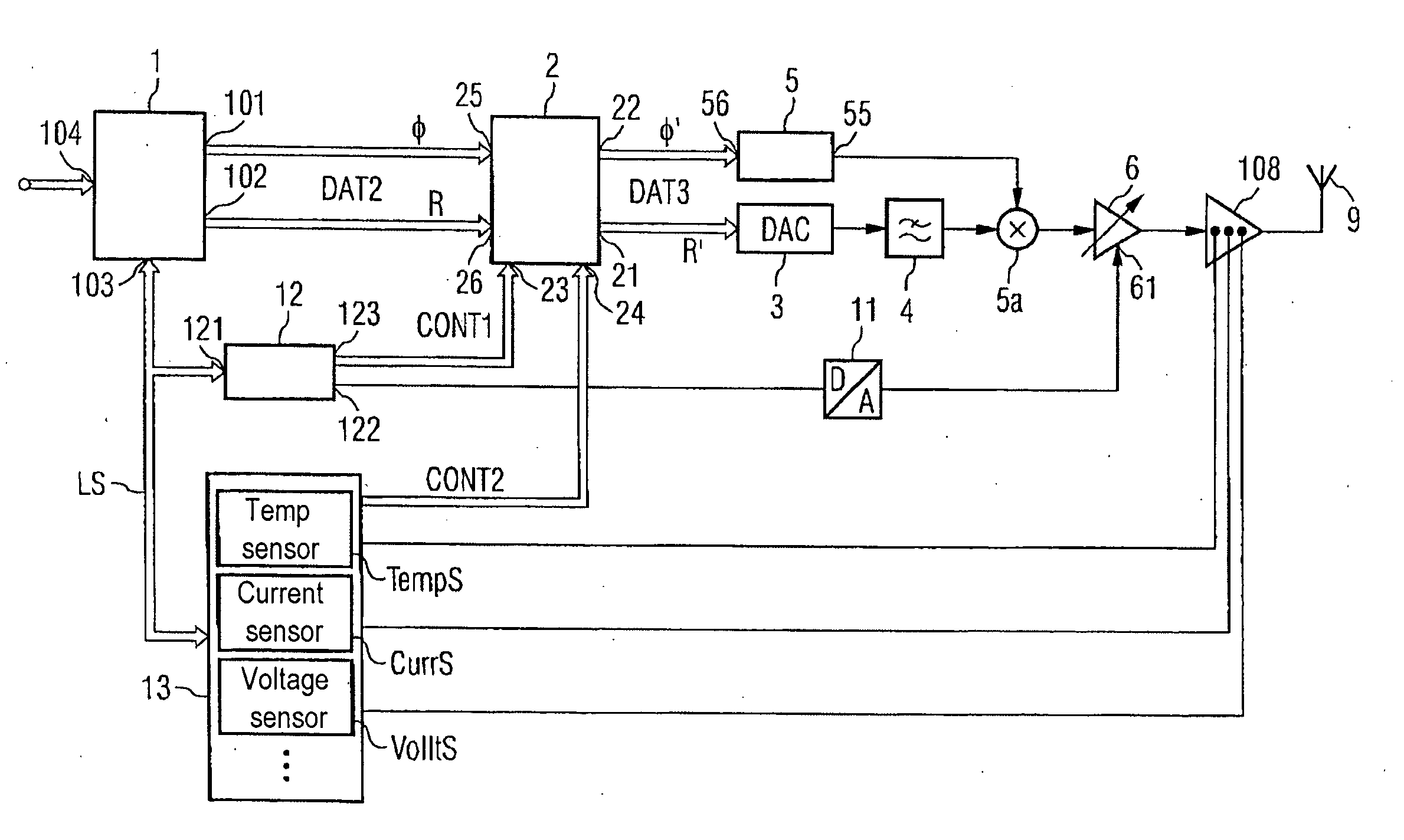
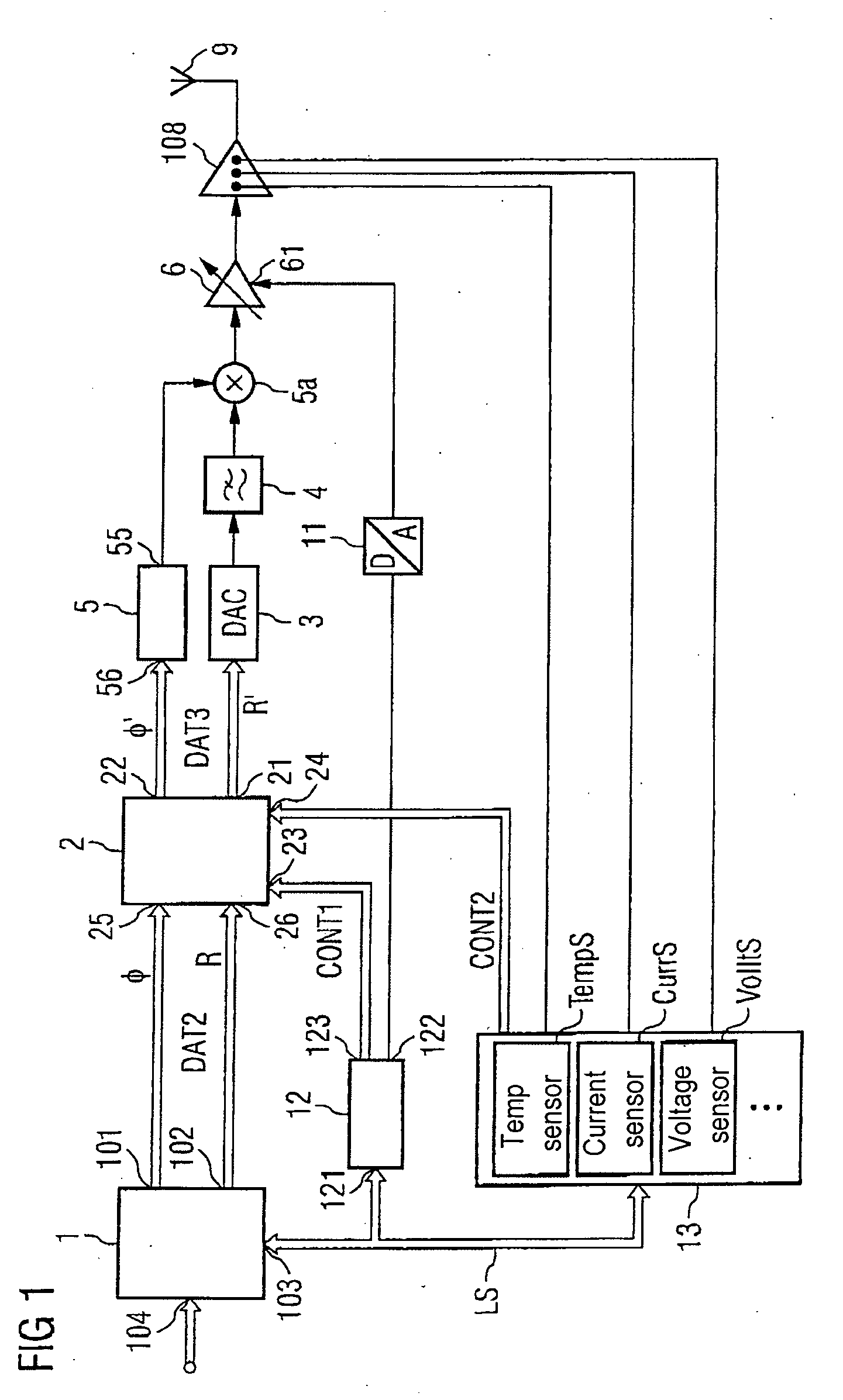
[0063]FIG. 1 shows one embodiment of a transmitting device with a predistortion unit which is designed according to one embodiment of the invention. The transmitting device, in one example, is based not carrying out continuous predistortion of a signal to be transmitted. Instead, predistortion of the so-called digital baseband signal is carried out selectively; that is, whenever the requirements for the linearity of the signal to be emitted from the transmitting device can no longer be complied with an undistorted baseband signal.

[0064] Non-linear signal components in the signals to be emitted result from circuits and / or components which have a non-linear area in at least a part of their characteristic being provided in the transmission path of the transmitting device. If the drive level and the amplitude at the circuits and the input signals applied to the components lead to the circuits and / or components being operated in the non-linear ranges, then the output signal contains add...


PUM


Abstract

A transmitting device with digital predistortion is disclosed. The device produces a power word derived from an amplitude component of a digital modulation signal and a desired output power. The power word is compared with a limit value, and depending on the result, one pair of predistortion coefficients is selected and distortion of a first and second component of the digital modulation signal is thus carried out. The phase and the amplitude of a carrier signal are then modulated with the distorted components. Selective distortion of the modulation signal is carried out by comparison of the power word with a limit value, when the signal quality or the linearity of the modulated carrier signal falls below a predetermined limit value. Otherwise, the predistortion unit can be switched off, and the power consumption can thus be reduced.

Description

REFERENCE TO RELATED APPLICATIONS [0001] This application claims the benefit of the priority date of German application DE 10 2005 013 881.0, filed on Mar. 24, 2005, the contents of which are herein incorporated by reference in their entirety. FIELD OF THE INVENTION [0002] The invention relates to a method for signal processing, and to a transmitting device with digital predistortion, for example, for mobile radio. BACKGROUND OF THE INVENTION [0003] The requirements of modern communication standards for the signal quality of transmitting devices and transceivers are becoming more stringent as the need for high data rates and increasing mobility grow. Mobile radio standards which have been used until now such as UMTS / WCDMA, GSM / EDGE, W-LAN or Bluetooth Medium Rate, use bandwidth-efficient modulation types for transmission of high data rates both from a base station to a mobile appliance and from a mobile appliance to a base station. Examples of these modulation types are QPSK (Quadra...

Claims


Application Information

Patent Timeline
IPC IPC(8): H03F1/26
CPCH03F1/0205H03F1/0211H03F1/0261H03F1/30H03F1/32H04L27/368H03F3/24H03F2200/331H03F2200/372H03F2200/447H03F1/3241
Inventor MULLER, JAN-ERIKCEYLAN, NAZIM
Owner INFINEON TECH AG
Why Eureka
Try Eureka