Compact optical detection system for a microfluidic device
- Summary
- Abstract
- Description
- Claims
- Application Information
AI Technical Summary
Benefits of technology
Problems solved by technology
Method used
Image
Examples
Embodiment Construction
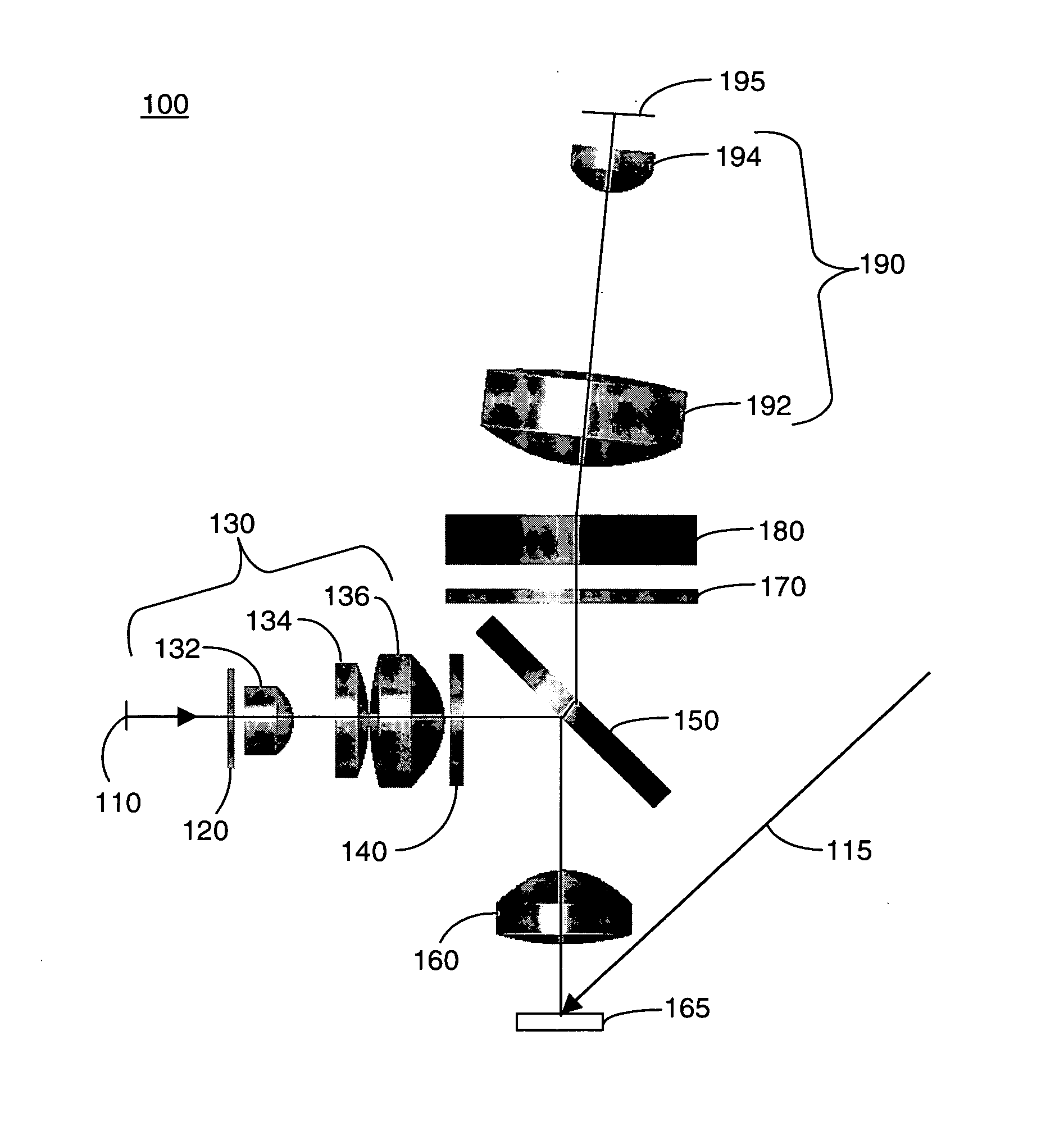
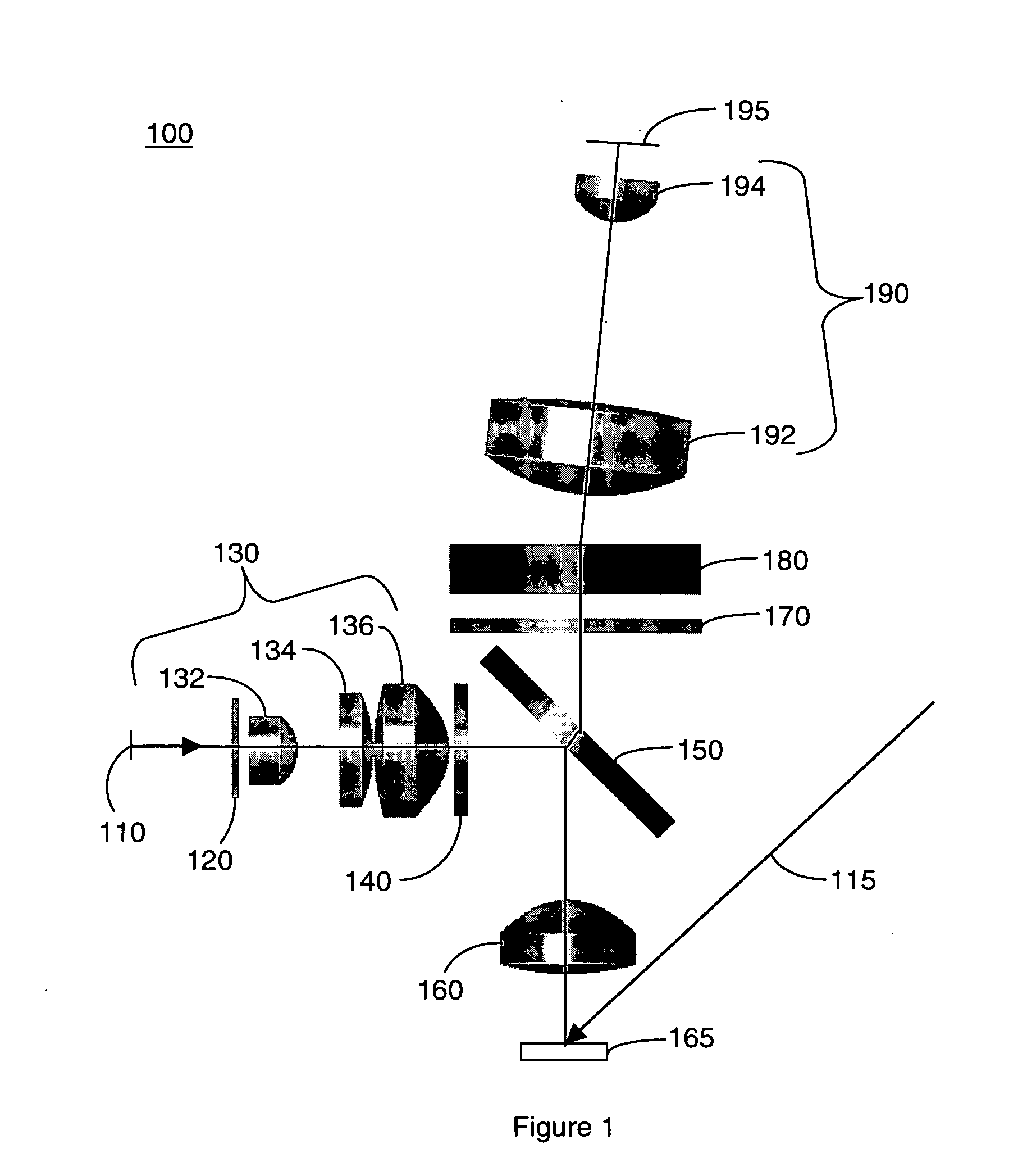
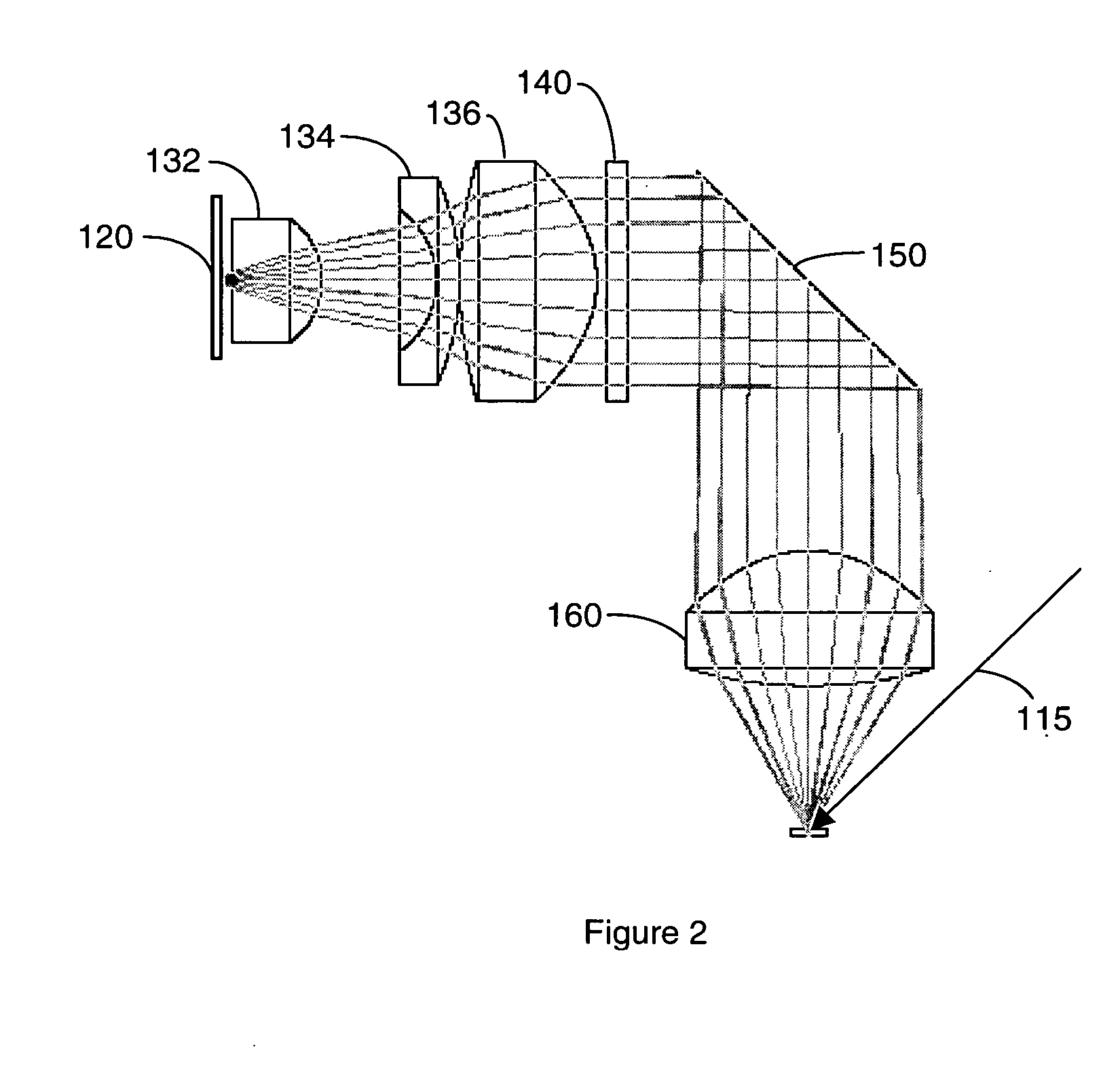
[0020] One aspect of the present invention is an optical detection system. One embodiment of the system, in accordance with the present invention, is illustrated in FIG. 1 at 100. In the present nonlimiting example, system 100 comprises an LED light source 110; a slit 120; a slit lens 130 comprising three slit lens elements 132, 134, and 136; an excitation bandpass filter 140; a beam splitter 150, an objective lens 160; a rejection filter 170; a diffraction grating 180; a CCD lens 190 comprising CCD lens elements 192 and 194; and a CCD array 195. A second light source, which may be either a laser or an LED, is indicated at 115. A microfluidic device is indicated at 165.
[0021] Slit 120 is back illuminated by LED 110. The LED may be used in place of or in addition to a laser light source, as will be explained below. The size, shape, wavelength, and power level of the LED may be varied. LEDs are currently available in various colors, including UV, blue, cyan, and green, representing e...
PUM
 Abstract
Description
Claims
Application Information
 - R&D
- Intellectual Property
- Life Sciences
- Materials
- Tech Scout
- Unparalleled Data Quality
- Higher Quality Content
- 60% Fewer Hallucinations
Browse by: Latest US Patents, China's latest patents, Technical Efficacy Thesaurus, Application Domain, Technology Topic, Popular Technical Reports.
© 2025 PatSnap. All rights reserved.Legal|Privacy policy|Modern Slavery Act Transparency Statement|Sitemap|About US| Contact US: help@patsnap.com


