Tunable laser

a laser and tunable technology, applied in the direction of laser details, semiconductor lasers, electrical devices, etc., can solve the problems of discontinuities in the output spectrum of the above-mentioned design, and achieve the effects of stable and inexpensive design, broad tuning range, and few or with closely controlled mode hops

Inactive Publication Date: 2006-10-12
COHERIX
View PDF5 Cites 9 Cited by
  • Summary
  • Abstract
  • Description
  • Claims
  • Application Information

AI Technical Summary

Benefits of technology

[0007] It is an object of the invention to produce a tunable laser apparatus, system, and method which is stable and inexpensive, and which provides a broad tuning range with few or with closely controlled mode hops.

Problems solved by technology

The above mentioned design is susceptible to discontinuities in the output spectrum.

Method used


Image

  • Tunable laser
  • Tunable laser
  • Tunable laser

Examples


Embodiment Construction

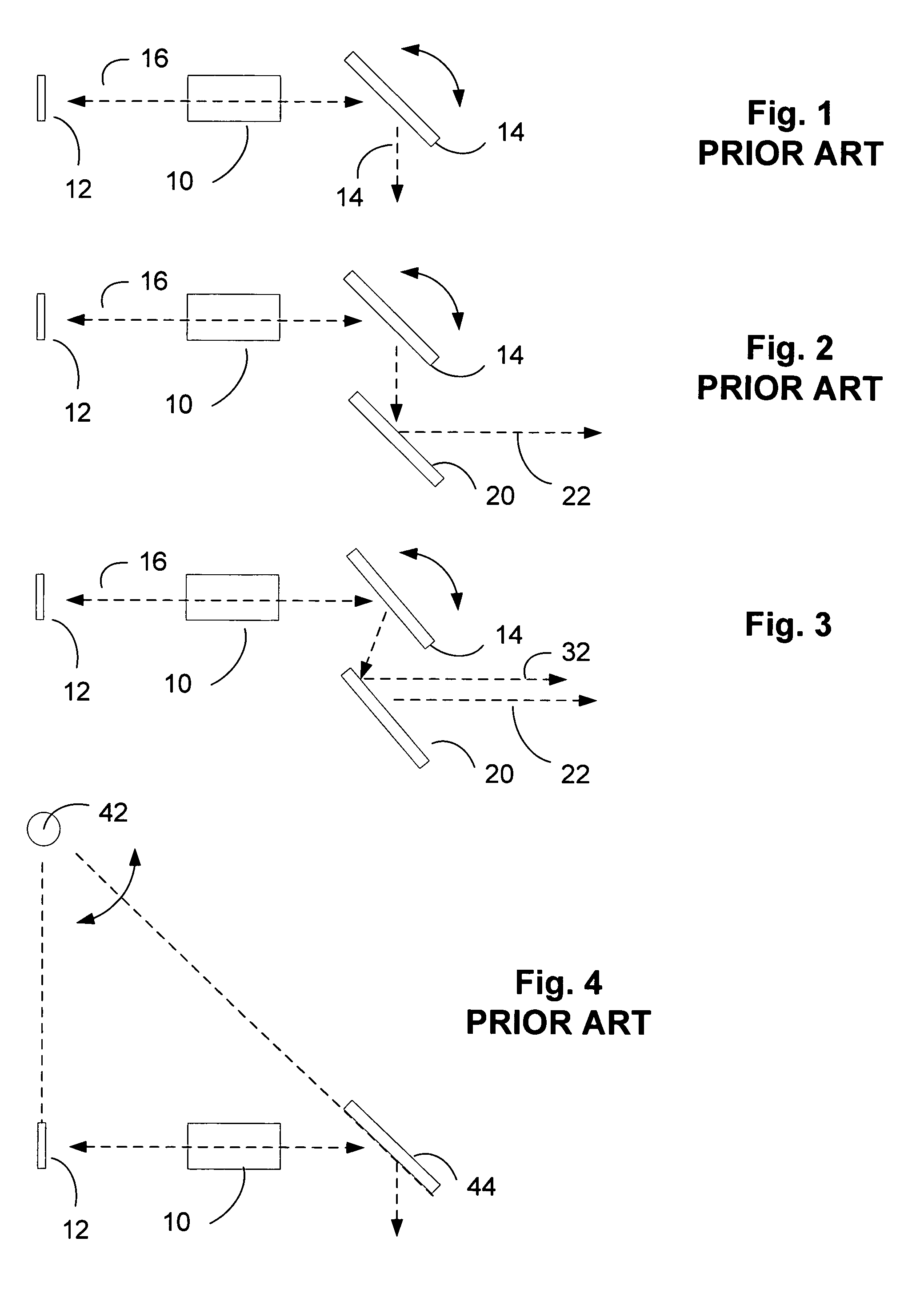
[0019]FIG. 1 depicts a tunable laser cavity set up with a laser amplification module 10, a rear reflector 12, and a tuning module 14. Light 16 is reflected back and forth between reflector 12 and module 14, and is amplified by module 10. Amplification module 10 may contain a gas, liquid, or solid medium as active medium. Fluorescent dyes in solution and semiconductor devices are among the most popular media for amplification because they exhibit rather large gain bandwidths, but doped optical fibers and Raman effect amplifiers, and Raman active fluid filled fibers are also anticipated by the inventor. Tuning module 14 is represented in FIG. 1 as a grating set up to diffract a non-zero grating order back to the amplification module. The grating is rotatable about an axis so that different wavelengths of light may be fed back and amplified to produce laser light. The laser output beam 18 is shown in FIG. 1 as the reflected zero order diffracted beam from the grating. Other well known ...


PUM


Abstract

A tunable extended cavity laser is disclosed having a single flexure pivot or hinge forming a pivot axis about which a grating tuning element is rotated. The pivot axis does not move appreciably as the grating is pivoted. The most preferred embodiment of the flexure hinge is a cartwheel hinge.

Description

FIELD OF THE INVENTION [0001] The field of the invention is the field of tunable lasers. BACKGROUND OF THE INVENTION [0002] The basic principles of the operation of the tunable laser utilizing a variable length external cavity in conjunction with a diffraction grating and a rotatable mirror are set forth in the publication, “Spectrally Narrow Pulse Dye Laser Without Beam Expander,” by Michael G. Littman and Harold J. Metcalf, Applied Optics, vol. 17, No. 14, pages 2224-2227, Jul. 15, 1978. Although the article describes a system which uses a dye laser, the diode laser is easily substituted. The system utilizes a diffraction grating which is filled with an incident collimated laser beam by using the grating at a grazing angle. The diffracted beam at the angle normal to the mirror is reflected back onto the grating and from there it is diffracted in a direction opposite the original collimated beam. The first order of diffraction of the grating is incident on the mirror, which reflect...

Claims


Application Information

Patent Timeline
Patent Type & Authority Applications(United States)
IPC IPC(8): H01S3/10
CPCH01S3/1055H01S5/143H01S5/141H01S5/02252H01S5/02326
Inventor KLOOSTER, ALEX
Owner COHERIX
Why Eureka
Try Eureka