Stress relief grooves for Francis turbine runner blades

a technology of francis turbine and runner blade, which is applied in the direction of propellers, propulsive elements, water-acting propulsive elements, etc., can solve the problems of affecting the hydraulic flow of water past the blade, the blades of the above mentioned francis-type runners may be subject to failure, and the application is not acceptabl

Inactive Publication Date: 2006-10-12
GENERAL ELECTRIC CANADA MISSISSAUGA
View PDF4 Cites 2 Cited by
  • Summary
  • Abstract
  • Description
  • Claims
  • Application Information

AI Technical Summary

Benefits of technology

[0006] The present invention relates to a runner for a Francis-type hydraulic turbine where each runner blade has an outlet edge with at least one stress relieving groove cut through the blade from...

Problems solved by technology

The blades of the aforementioned Francis-type runners may be subject to failure adjacent the junctions of the trailing outlet edge of the blade with the crown and band due to fatigue...

Method used


Image

  • Stress relief grooves for Francis turbine runner blades
  • Stress relief grooves for Francis turbine runner blades
  • Stress relief grooves for Francis turbine runner blades

Examples


Embodiment Construction

[0016] The present invention relates to hydraulic machines and in particular to improvements in runners for Francis-type machines.

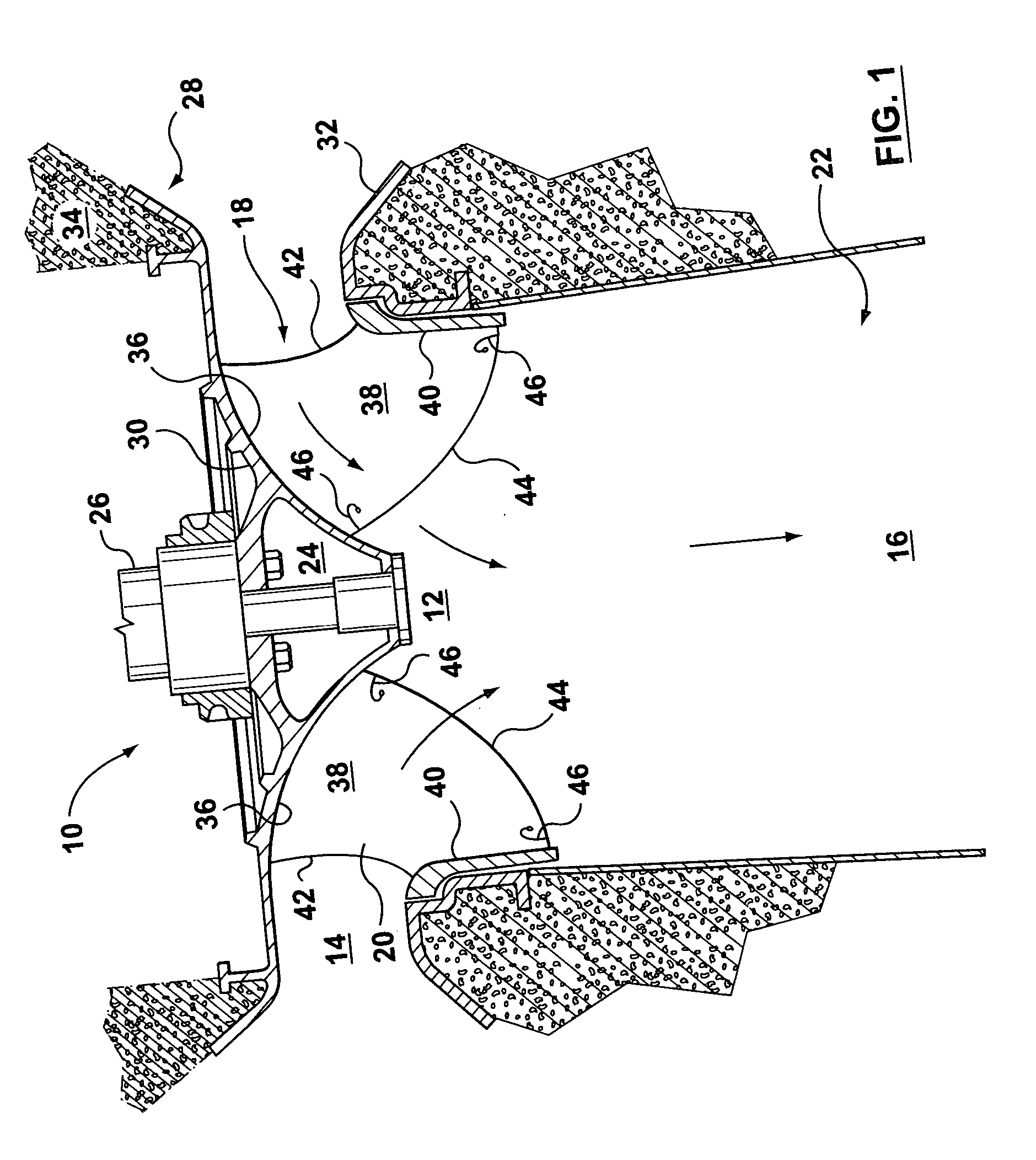
[0017] Referring to FIG. 1, an exemplary turbine installation 10 is illustrated for use in the generation of hydroelectricity which may benefit from the present invention. The installation 10 has a water passageway 12. Water flows from an inlet 14 of passageway 12 to an outlet 16 located at a lower elevation. The water passageway 12 passes through a Francis turbine 18 having a runner 20 and a draft tube 22. The runner 20 is secured by bolts 24 to a shaft 26 transmitting energy to a generator (not shown). The turbine 18 is mounted in a stationary casing 28 having a head cover 30 and a bottom discharge ring 32. The head cover 30, discharge ring 32 and draft tube 22 are embedded in concrete foundation 34. It should be understood that installation 10 includes other components such as, for example, stay vanes and wicket gates which are not shown.
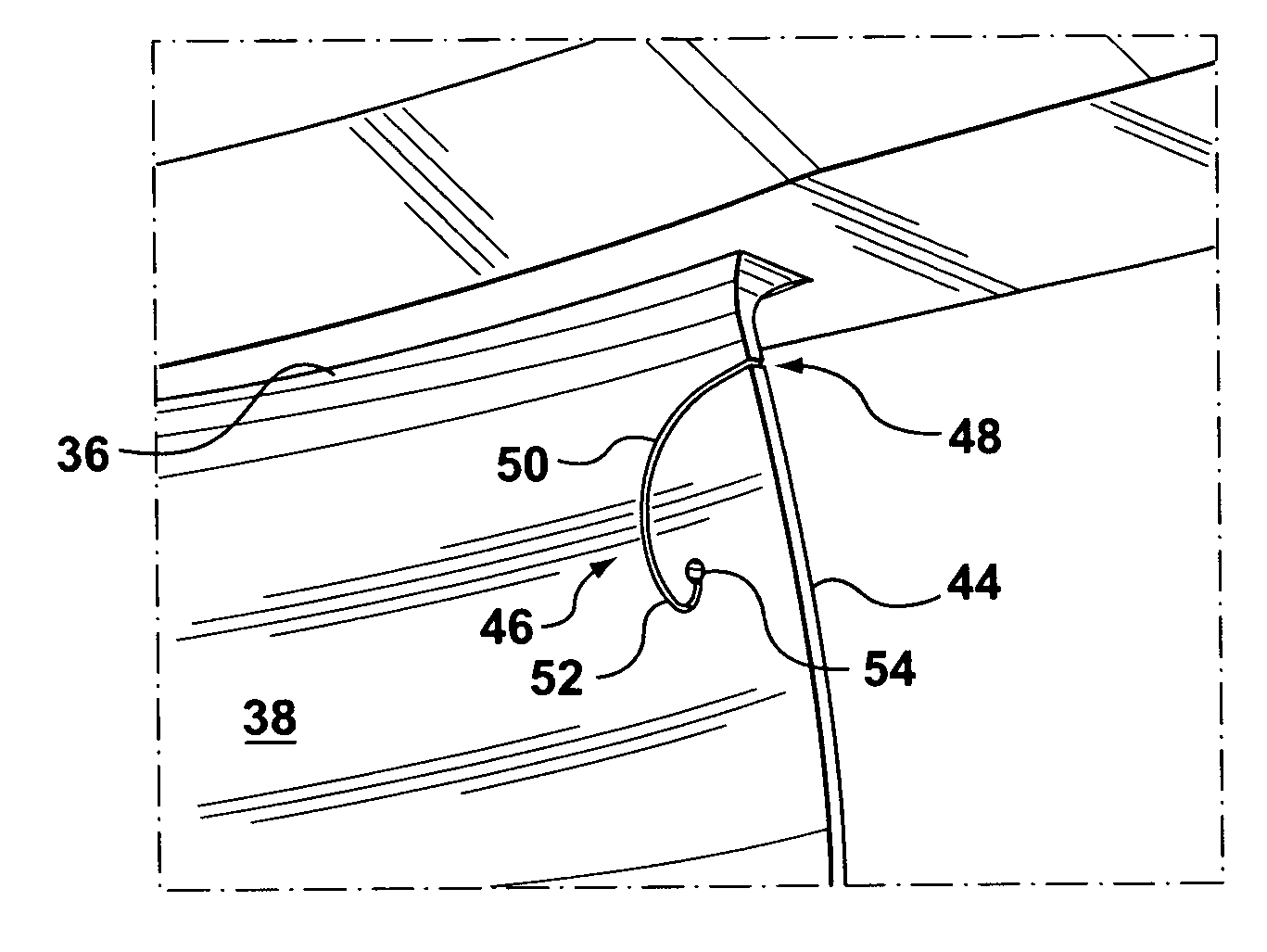
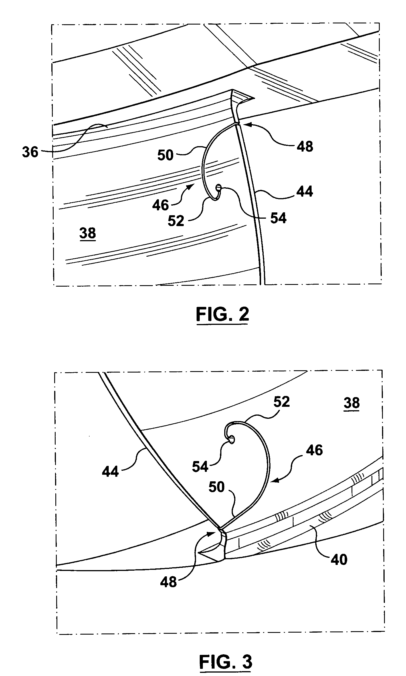
[0018] Runne...


PUM


Abstract

There is disclosed a runner for a Francis-type hydraulic turbine where each runner blade has an outlet edge with two stress relieving grooves cut through the blade from the outlet edge adjacent the crown and the band. The grooves each present an opening across the outlet edge and the grooves each extend a predetermined distance from the outlet edge into the blade.

Description

BACKGROUND OF THE INVENTION [0001] The present invention relates to hydraulic machines and in particular to improvements in runner blades for Francis-type machines. [0002] Conventional Francis-type runners comprise a crown with a concentric band or ring and an array of blades extending between and interconnecting the crown with the ring. The runner is rotated about the axis of the crown by the action of water passing through a plurality of flow paths formed between each pair of adjacent blades in the array of blades. Each of the blades has a leading flow dividing edge which defines the line of demarcation between a suction surface leading in the direction of rotation and a trailing pressure surface trailing in the direction of rotation. This edge, at the inlet of the blades, is normally oriented to slope from the band toward the crown to advance in the direction of rotation of the runner. Water enters the periphery of the runner and passes over the blades and leaves the runner axial...

Claims


Application Information

Patent Timeline
IPC IPC(8): F03B3/12
CPCF03B3/121Y02E10/223F05B2240/241F03B3/125Y02E10/20Y10S416/50
Inventor HUBER, PAUL
Owner GENERAL ELECTRIC CANADA MISSISSAUGA
Why Eureka
Try Eureka