Implantable RF telemetry devices with power saving mode

Active Publication Date: 2006-10-12
MICROSEMI SEMICON
View PDF11 Cites 93 Cited by
  • Summary
  • Abstract
  • Description
  • Claims
  • Application Information

AI Technical Summary

Benefits of technology

[0007] According to the present invention there is provided an implantable electronic device, comprising a first radio receiver for receiving telemetry data, said first radio receiver having a wake mode and a sleep mode, and being configured to be normally in said sleep mode; a second radio receiver with very low power consumption compared to said first radio receiver; a control unit for periodically turning on the second radio receiver during a sniff period to listen for an incoming rad

Problems solved by technology

However, since the battery capacity in an implantable device is very limited, the introduction of a RF transceiver operating at 402-405 MHz becomes a real challenge.
A trickier problem is the issue of waking up the RF component from the off state to start communications in a reasonable amount of time without draining the

Method used


Image

  • Implantable RF telemetry devices with power saving mode
  • Implantable RF telemetry devices with power saving mode

Examples


Embodiment Construction

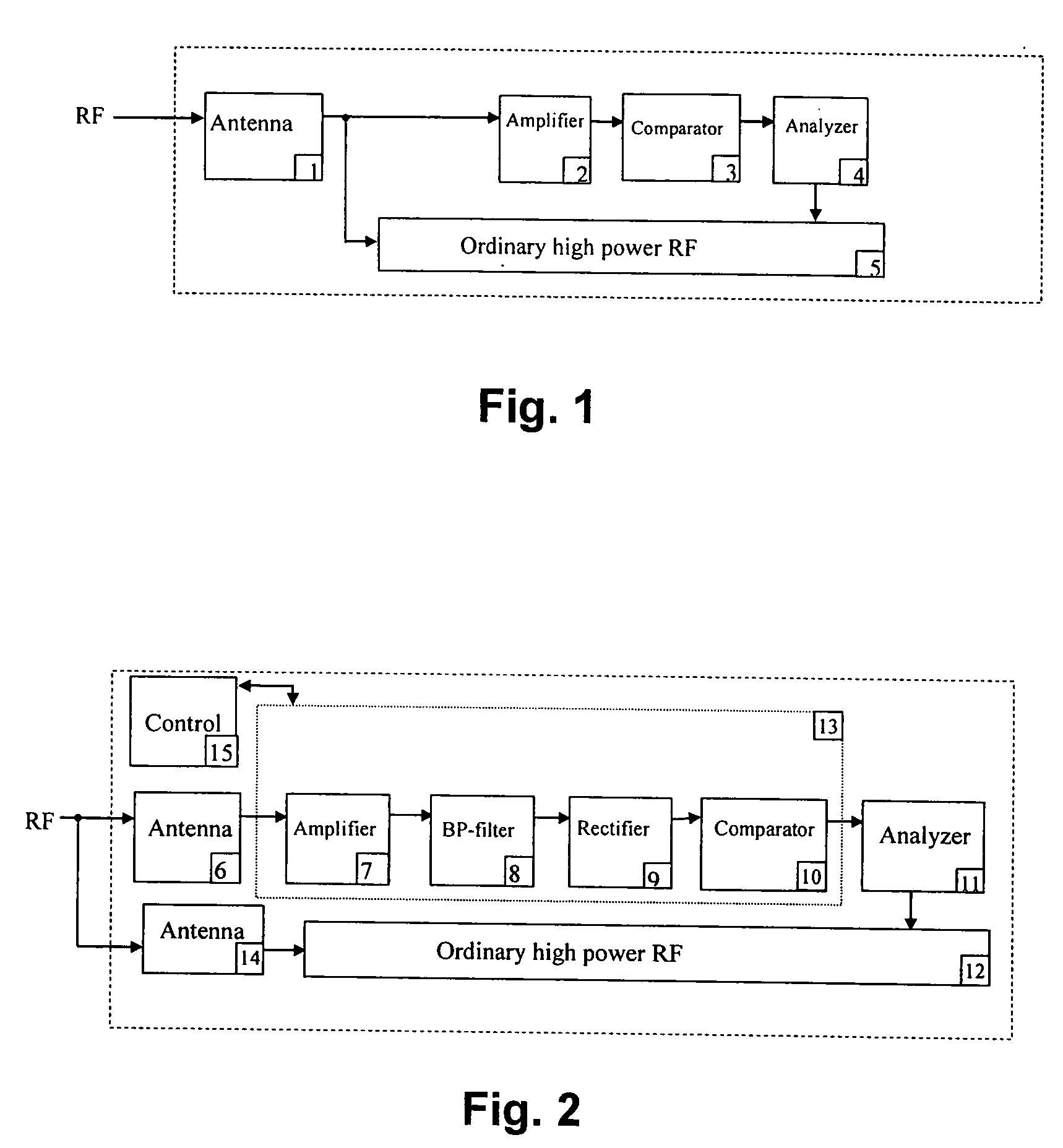
[0017] Referring to FIG. 1, the simplified receiver comprises an antenna 1 receiving a wake-up signal (common with the MICS band antenna or separate), an amplifier 2 which amplifies the signal, and a comparator / detector 3 that detects the amplified signal if it is above a certain power level.

[0018] To further increase the security of the receiver against the device being woken up by noise, the wake-up signal comprises a predetermined coded pattern, which is analyzed in an analyzer 4 to see if it matches the wake-up pattern. Only if the pattern is correct the full transceiver 5 will be turned on by the analyzer 4. The amplifier 2, comparator 3 and analyzer 4 form part of a simple very low power receiver.

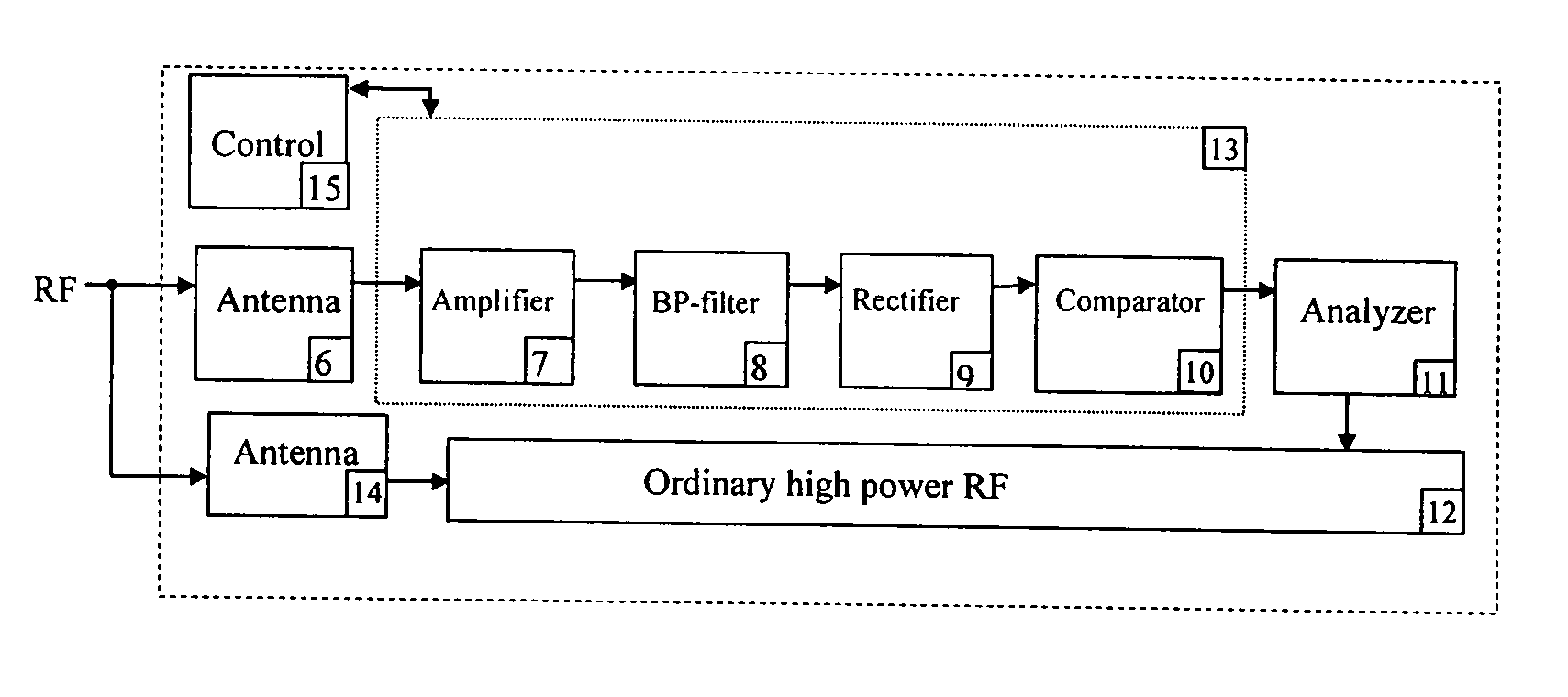
[0019]FIG. 2 shows another embodiment where an RF signal is received by a tuned antenna 6 connected to an amplifier 7, an optional band pass filter 8, which in turn is connected to a rectifier 9, connected to a comparator 10, which is connected to an analyzer 11. The analyzer 11 is ...


PUM


Abstract

An electronic implantable device with a power saving circuit incorporates a radio frequency receiver with low power consumption. A high power radio receiver is normally turned off during a period of inactivity. When an analyzer detects a predetermined identification code in a received radio frequency signal, it outputs a signal to turn on the high power receiver.

Description

BACKGROUND OF THE INVENTION [0001] 1. Field of the Invention [0002] This invention describes a method of saving power in an implantable device, such as a pacemaker, which includes RF telemetry functionality. [0003] 2. Description of Related Art [0004] Since the allocation of a special frequency band for implantable medical devices using RF telemetry, the so-called MICS (Medical Implantable Communication Service) band, by FCC in the late 1990's, the development of devices including this functionality has really taken off. However, since the battery capacity in an implantable device is very limited, the introduction of a RF transceiver operating at 402-405 MHz becomes a real challenge. If the transceiver operates at 5 mA in the active mode, this might be acceptable since in the normal user scenario the on-time is only a fraction (<0.01%) of the total device life time. A trickier problem is the issue of waking up the RF component from the off state to start communications in a reaso...

Claims


Application Information

Patent Timeline
IPC IPC(8): H04B1/16H04B1/38H04M1/00A61N1/372A61N1/378
CPCA61N1/37223A61N1/378A61N1/37276
Inventor SIVARD, AKE
Owner MICROSEMI SEMICON
Why Eureka
Try Eureka