Injection device with secondary reservoir

a secondary reservoir and injection device technology, applied in the direction of respirator, infusion syringe, breathing protection, etc., can solve the problems of fluid “jetting”, discomfort for patients or self-injectors, and current typical subcutaneous injection system used for subcutaneous delivery is not believed to be optimal for general us

Active Publication Date: 2006-10-12
EMBECTA CORP
View PDF17 Cites 339 Cited by
  • Summary
  • Abstract
  • Description
  • Claims
  • Application Information

AI Technical Summary

Benefits of technology

[0011] An object of one aspect of the present invention is to provide an injection device that can inject medication into the intradermal tissue layer with a comparable amount of force as that required to inject medication into the subcutaneous tissue region.

Problems solved by technology

Injections into the subcutaneous and intramuscular tissue layers can cause discomfort to the patient or self-injector because of the characteristics of the tissue, needle length and needle diameter or gauge.
Current typical pen injection systems used for subcutaneous delivery are not believed optimal for use by the general population of self-injectors for delivery into the intradermal layer because of, inter alia, the high backpressures associated with injecting fluid into the intradermal layers of the skin using microneedles.
Further, the increased actuation force required to actuate the injector device may result in the fluid “jetting” past the desired tissue depth due to the increased fluid pressure.

Method used


Image

  • Injection device with secondary reservoir
  • Injection device with secondary reservoir
  • Injection device with secondary reservoir

Examples


Embodiment Construction

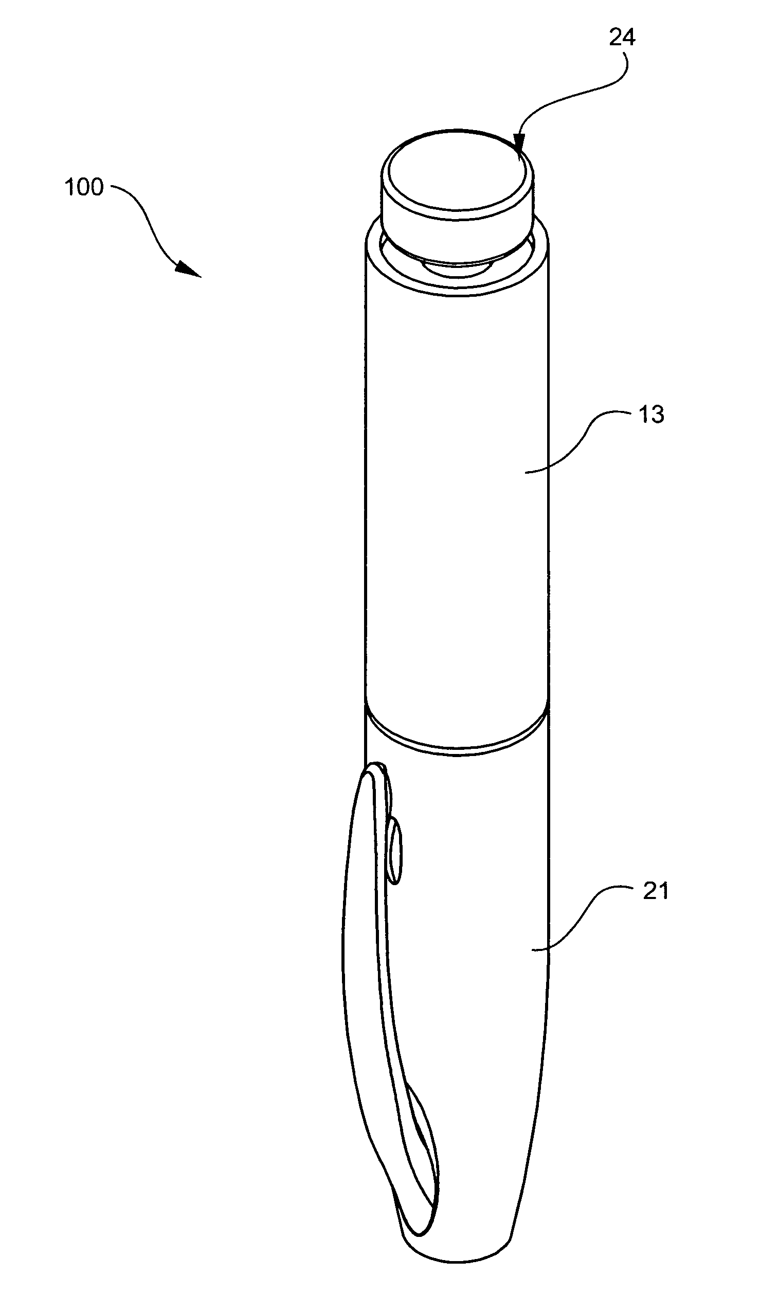
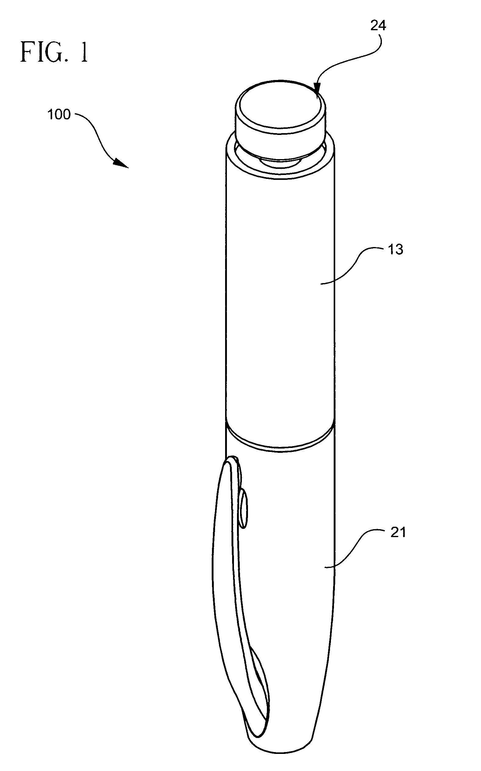
[0036] Pen injector devices, such as the exemplary pen injector 100, as shown in FIG. 1, typically comprise a dose knob / button 24, an outer sleeve 13, and a cap 21. The dose knob / button 24 allows a user to set the dosage of medication to be injected. The outer sleeve 13 is gripped by the user when injecting medication. The cap 21 is used by the user to securely hold the pen injector device 100 in a shirt pocket, purse or other suitable location.

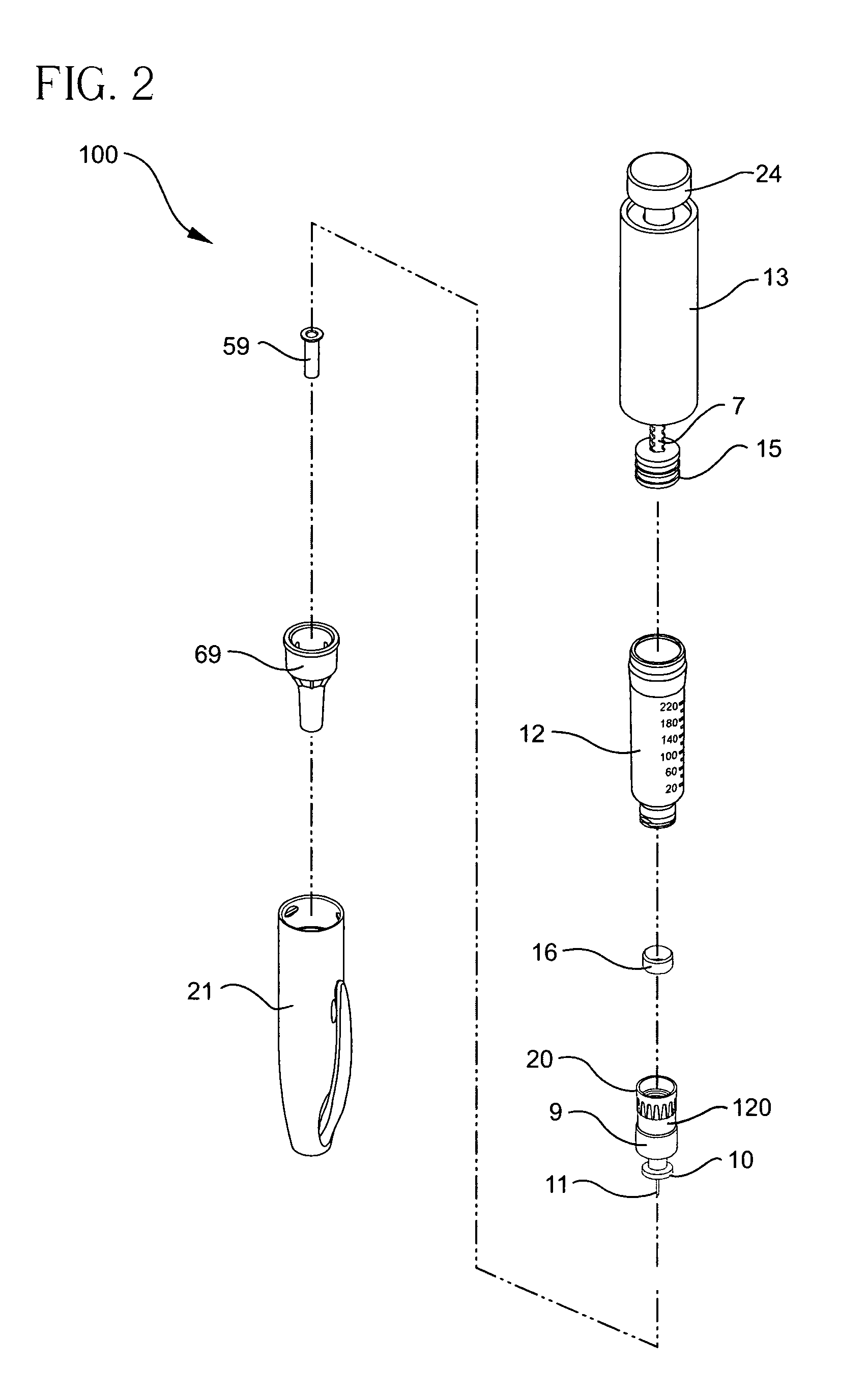
[0037]FIG. 2 is an exploded view of an exemplary pen injector device shown in FIG. 1. The dose knob / button 24 has a dual purpose and is used to both set the dosage of the medication to be injected and used to inject the dosed medicament via the lead screw 7 and stopper 15 through the medicament cartridge 12 attached to the invention through the reservoir housing 20. In standard pen injector devices the dosing and delivery mechanisms are all found within the outer sleeve 13 and is not described in greater detail here as they are understood by...


PUM


Abstract

A method and apparatus for injecting fluid into areas having high density tissue that creates a high backpressure resistance on the injection device is disclosed. The high backpressure resistance is overcome through a mechanical advantage achieved by using a secondary reservoir having a cross-sectional area smaller than the cross-sectional area of a primary reservoir. Exemplary injection device reservoir housings may comprise a primary reservoir, a secondary reservoir, a check valve, a septum penetrating cannula, travel limits, a pen needle connecting portion, sliding seal guide ribs, a sliding seal, a pen needle assembly, a needle stop, and a patient needle.

Description

CROSS-REFERENCE TO RELATED APPLICATION [0001] The subject matter of this application is related to that of U.S. patent application Ser. No. 10 / 238,958, filed Sep. 11, 2002, the entire disclosure of which is hereby incorporated by reference. The subject matter of this application is also related to that of a U.S. Patent Application of Lovell et al., entitled “Injector Device With Force Lock-Out And Injection Rate Limiting Mechanisms”, Attorney Docket No. P-6414 (47685), filed concurrently herewith, the entire disclosure of which is incorporated herein by reference.FIELD OF THE INVENTION [0002] The present invention relates generally to the delivery of medication using injection devices. Specifically, one implementation of the invention relates to injection devices and methods that incorporate a secondary pre-delivery reservoir in a microneedle medication delivery device to provide a mechanical advantage. BACKGROUND OF THE INVENTION [0003] In certain circumstances, it is desirable to ...

Claims


Application Information

Patent Timeline
Patent Type & Authority Applications(United States)
IPC IPC(8): A61M5/178
CPCA61M5/204A61M5/283A61M5/3155A61M2005/3128A61M5/3158A61M5/46A61M5/31561
Inventor MARSH, RONALD W.FOLLMAN, MARKBROWKA, EDWARD P.
Owner EMBECTA CORP
Why Eureka
Try Eureka