Heat dissipating device

a heat exchanger and surface technology, applied in lighting and heating apparatus, electrical apparatus, cooling/ventilation/heating modifications, etc., can solve the problems of reducing efficiency, reducing heat dissipation efficiency, so as to increase the restriction of fluid flow and increase the heat transfer coefficient

Inactive Publication Date: 2006-10-19
US THERMOELECTRIC CONSORTIUM
View PDF42 Cites 48 Cited by
  • Summary
  • Abstract
  • Description
  • Claims
  • Application Information

AI Technical Summary

Benefits of technology

[0018] The invention utilizes a hybrid of star pins with concave surfaces and sharp edges, and truncated dimples, which create an extraordinary turbulence phenomenon in f...

Problems solved by technology

Past innovations to increase the heat transfer coefficient and simultaneously enhancing cooling by extending heat exchanger surfaces in a manner that substantially improves heat dissipation have experienced average to poor results.
These surface textures have been an attempt to enhance heat exchanging capabilities; however, they have, in fact, actually decreased turbulence near the surfaces as turbulent flow has been converted to less efficient laminar fluid flow.
Another compounding efficiency limitation in previous art has been when solutions are attempted with a focus on turbulent flow.
Previous art has implemented the use of turbulence, but with a negative result because the resultant turbulence has actually restricted fluid flow through the exchanger, therefore reducing efficiencies.
However, the high pin density with sharp edges in close proximity actually substantially reduced fluid flow more dramatically thus not significantly improving heat transfer efficienc...

Method used


Image

  • Heat dissipating device
  • Heat dissipating device
  • Heat dissipating device

Examples


Embodiment Construction

[0069] Referring more specifically to the drawings, for illustrative purposes the present invention is embodied in the apparatus generally shown in FIG. 1A through FIG. 17. It will be appreciated that the apparatus may vary as to configuration and as to details of the parts, and that the method may vary as to the specific steps and sequence, without departing from the basic concepts as disclosed herein.

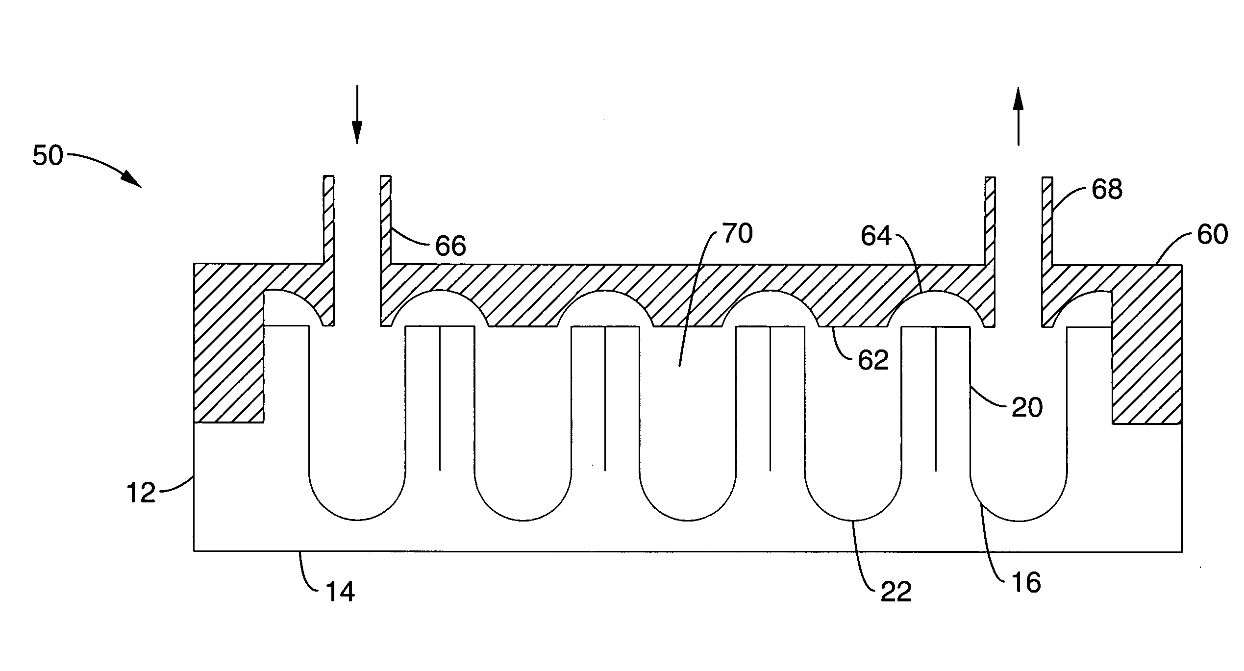
[0070] For liquid heat exchangers, increased surface area at the fluid interface surface and turbulent flow are desired for improved heat transfer. However, turbulent flow restricts fluid flow decreasing overall efficiency. Thus a balance of turbulent flow for heat transfer and laminar flow for fluid flow is desired. A heat transfer surface having pins perpendicular to the flow increases surface area and turbulent flow and is commonly used in a heat dissipating device.

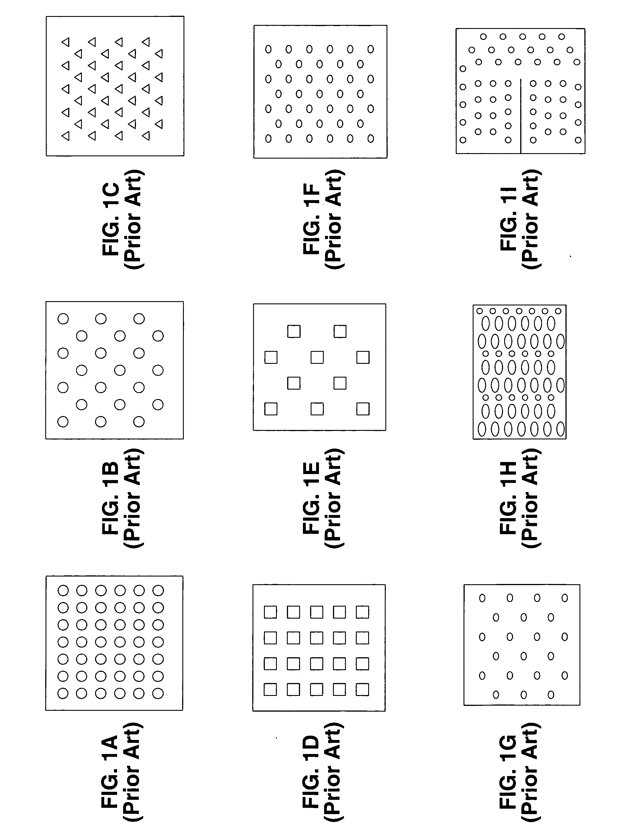
[0071]FIG. 1A through FIG. 1I illustrate top views of pin patterns used for heat dissipating devices in the known ar...


PUM


Abstract

A heat dissipation device with a fluid cavity that utilizes a hybrid of star pins with concave surfaces and sharp edges, and truncated dimples, which creates turbulence and a vortex phenomenon perpendicular to fluid flow transmission, and increases the heat transfer coefficient without increasing restriction of fluid flow through the device. This process increases the heat transfer along local pins which are located around each truncated dimple. This effect allows the use of taller pins than previous devices thus increasing the surface of heat transfer and thus these pins have a more efficient heat transfer coefficient along the total length of the pin, not possible previously. Star pins with sharp edges prevent the distortion of the highly efficient vortex flow which increases fluid flow and simultaneously intensifies the desired phenomena of extraordinary turbulence.

Description

CROSS-REFERENCE TO RELATED APPLICATIONS [0001] This application claims priority from U.S. provisional application Ser. No. 60 / 671,778, filed on Apr. 14, 2005, which is incorporated herein by reference in its entirety.STATEMENT REGARDING FEDERALLY SPONSORED RESEARCH OR DEVELOPMENT [0002] Not Applicable INCORPORATION-BY-REFERENCE OF MATERIAL SUBMITTED ON A COMPACT DISC [0003] Not Applicable NOTICE OF MATERIAL SUBJECT TO COPYRIGHT PROTECTION [0004] A portion of the material in this patent document is subject to copyright protection under the copyright laws of the United States and of other countries. The owner of the copyright rights has no objection to the facsimile reproduction by anyone of the patent document or the patent disclosure, as it appears in the United States Patent and Trademark Office publicly available file or records, but otherwise reserves all copyright rights whatsoever. The copyright owner does not hereby waive any of its rights to have this patent document maintain...

Claims


Application Information

Patent Timeline
IPC IPC(8): H05K7/20
CPCH05K7/20254F28F3/022F28F3/12
Inventor SPOKOINY, MICHAELKERNER, JAMES M.LUX, CRAIG J.MAURUS, JAMES M.
Owner US THERMOELECTRIC CONSORTIUM
Why Eureka
Try Eureka