Thin-film evaporator

a thin film evaporator and evaporator technology, applied in evaporators/condensers, distillation separation, vapor condensation, etc., can solve the problems of thermal instability of liquids and substances, and achieve the effect of increasing the separation capacity and saving energy, preferably

Active Publication Date: 2006-10-19
VTU HLDG GMBH
View PDF5 Cites 23 Cited by
  • Summary
  • Abstract
  • Description
  • Claims
  • Application Information

AI Technical Summary

Benefits of technology

[0009] Efficient energy saving can be achieved in that the inner device is designed as a heat-exchange surface and preferably is connected to a supply line for the medium to be evaporated in order to preheat the medium to be evaporated.

Problems solved by technology

The result of this is just a short contact time with the heating surface so that thermally unstable liquids and substances, respectively, can also be used and are only exposed to a low evaporation temperature, in particular also under a vacuum or at a very low pressure.
Furthermore, thin-film evaporators are used for separation tasks if the product accumulating as a residue has poor flow properties and / or is prone to agglutinations.

Method used


Image

  • Thin-film evaporator
  • Thin-film evaporator
  • Thin-film evaporator

Examples


example 1

[0043] 780 g of fatty acid methyl ester was distilled at a pressure of 0.2 mbar in a thin-film evaporator according to FIG. 7—however, without a knitted wire fabric 27. The temperature of the heat transfer oil amounted to 165° C. The yield (distillate / amount used) of distillate amounted to 97.8%. A sample of the distillate was examined by scanning electron microscopy. Traces of salt crystals (size approx. 1 μm) were found.

[0044] The same starting product was distilled in the same apparatus under the same conditions, however, a knitted wire fabric 27 closed on the top side was placed over the internal cooling coil.

Result

[0045] A sample of the distillate was again examined with the scanning electron microscope. Neither traces of crystalline substances nor other impurities were found. A special advantage of the knitted wire fabric is that splashes of the medium to be evaporated do not reach the condenser 11 and thus do not get into the residue.

example 2

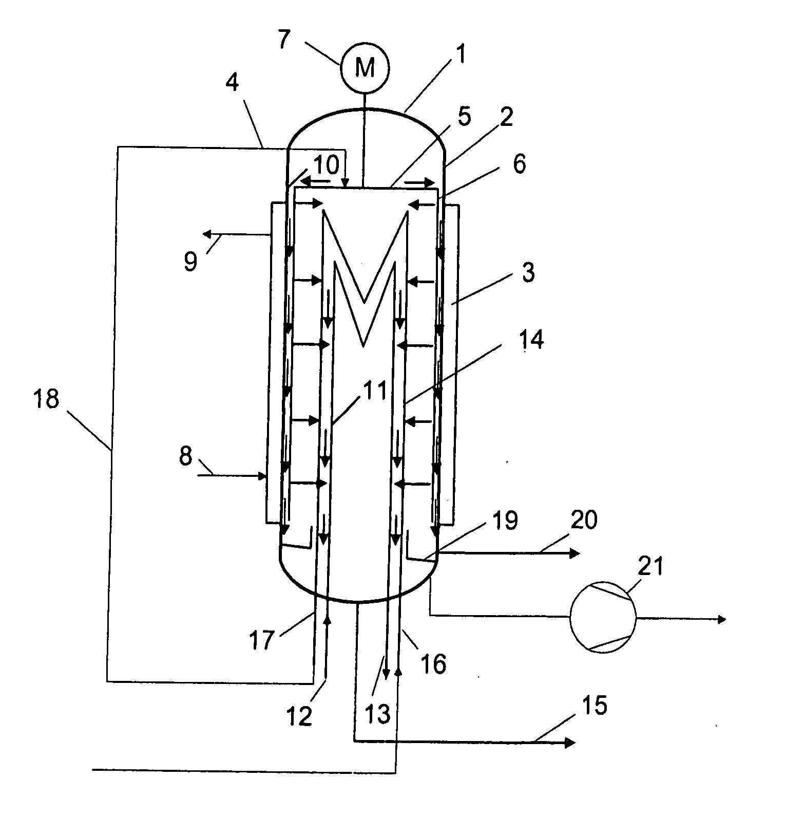
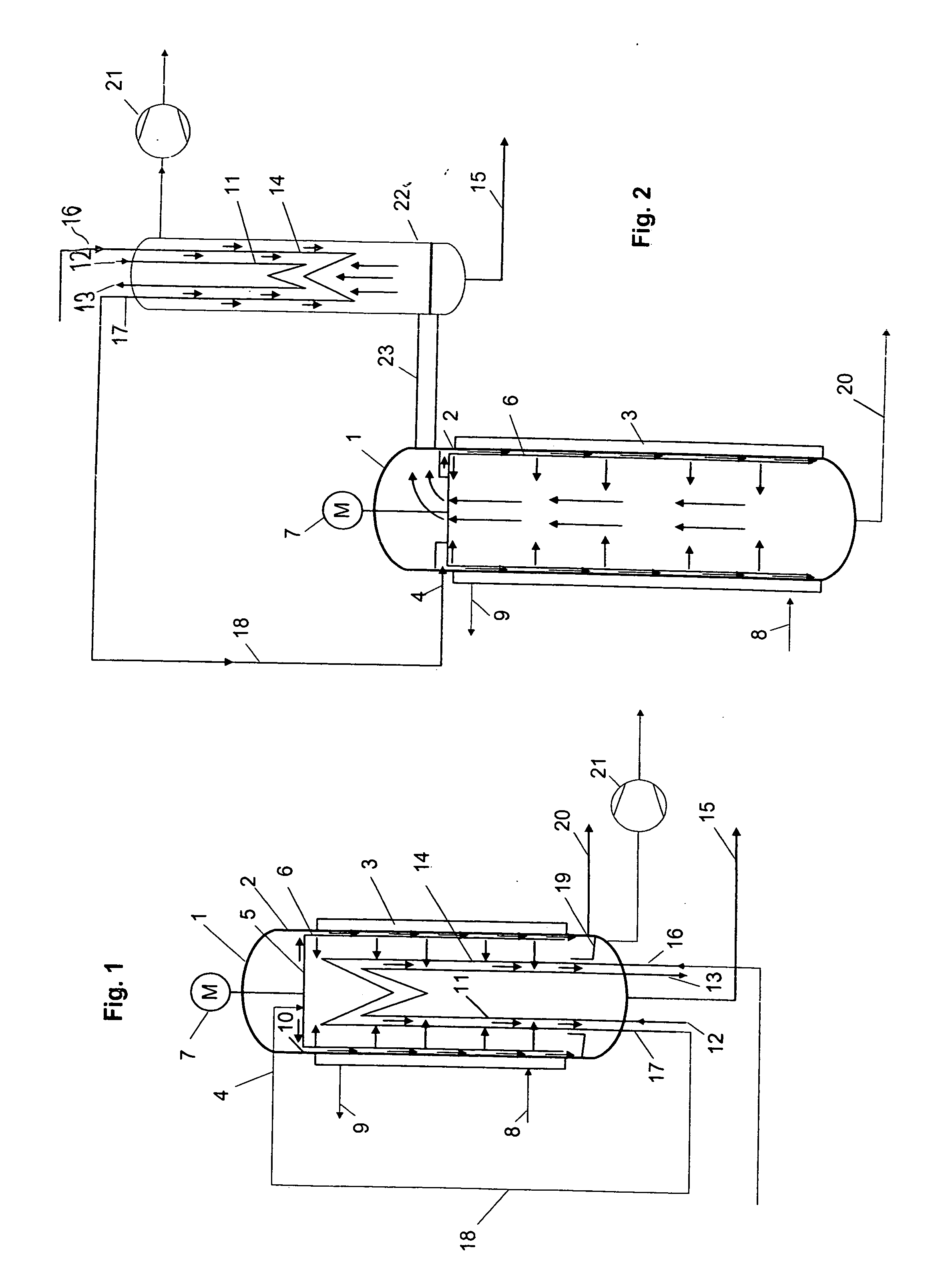
[0046] A thin-film evaporator according to FIG. 1—however, without a condenser 14—having an evaporator area of 9 m2 was continuously charged with a feed flow of 1,820 kg / h. The feed temperature amounted to 40° C. The evaporator was heated with high-pressure steam at 20 bar abs, with the heating temperature being adjusted via pressure valves. The distillation pressure amounted to 0.8 mbar. 1,690 kg / h was withdrawn as a distillate. The residue amounted to 112 kg / h. This is equivalent to a residue ratio (residue / distillate) of 6.6%. 598 kg / h of water vapour was consumed in this adjustment.

[0047] In a further step, the feed flow was conducted under constant conditions through a pipe coil which functioned as a preheater and as a condenser 14 and was wound around the central condenser 11.

Result

[0048] The feed temperature before entering the evaporator could be raised to 129° C. The steam consumption of the distillation decreased to 406 kg / h.

[0049] This is equivalent to an energy savin...

example 3

[0050] In two experiments, 800 g of a glycerol phase were distilled in each case at a pressure of 1.3 mbar in a thin-film evaporator according to FIG. 7—however, without a knitted wire fabric for the first experiment. The composition of the glycerol phase and of the distillate recovered in Experiment 1 (amount 656 g) can be seen in Table 1.

[0051] For Experiment 2, the following modifications were performed on the evaporator. A knitted wire fabric 27 (mesh width 1 mm; wire diameter approx. 0.2 mm; wound in several layers; total thickness approx. 4 mm) closed on the top side was placed over the internal condenser 11. The lower part was formed by a cylindrical pipe 28 which was designed such that it could be placed over the outlet nozzle 29 for the distillate and the waste gas, respectively, thus providing a separation between the condenser space 30 and the evaporator space 31. The partial contact of the knitted wire fabric 27 with the condenser 11 thus created the precondition for a ...


PUM

PropertyMeasurementUnit
pressureaaaaaaaaaa
temperatureaaaaaaaaaa
areaaaaaaaaaaa

Abstract

A thin-film evaporator comprising a vertical drum (1), a supply line (4) that is arranged in the upper region of the drum (1) and is used to supply a medium to be evaporated, a heating jacket (3) arranged on the periphery of the drum and forming vapours, a discharge line (20) for discharging the residue left in the lower end of the drum, and a condenser (11) supplied with a coolant, for increasing the separating capacity and optionally for performing chemical reactions, is characterized in that an inner device (24) influencing the action of the thin-film evaporator is provided in the path of the vapours from the heating jacket (3) to the condenser (11).

Description

[0001] This is a continuation of International Application No. PCT / AT2004 / 000335, filed on Oct. 1, 2004. BACKGROUND OF THE INVENTION [0002] The invention relates to a thin-film evaporator comprising a vertical drum, a supply line that is arranged in the upper region of the drum and is used to supply a medium to be evaporated, a heating jacket arranged on the periphery of the drum and forming vapours, a discharge line for discharging the residue left in the lower end of the drum, and a condenser supplied with a coolant. [0003] Temperature-sensitive substances such as, for example, pharmaceutical solutions or food concentrates may be heated to the boiling point only temporarily. So-called thin-film evaporators in which the medium to be evaporated or the solution to be concentrated by evaporation, respectively, is applied to the evaporator area only as a thin film serve for meeting this demand. The result of this is just a short contact time with the heating surface so that thermally u...

Claims


Application Information

Patent Timeline
Patent Type & Authority Applications(United States)
IPC IPC(8): B01D3/28B01D1/22B01D5/00B01J19/18
CPCB01D1/225Y10S159/20B01J19/1887B01D5/0006
Inventor WOLFGANG, GLASLMATTHAEUS, SIEBENHOFERMICHAEL, KONCAR
Owner VTU HLDG GMBH
Why Eureka
Try Eureka