Weld prep joint for electron beam or laser welding

a technology of electron beam or laser welding and weld prep, which is applied in the direction of turbines, manufacturing tools, machines/engines, etc., can solve the problems of unsatisfactory weld rotors, etc., and achieve the effect of eliminating internal rotor surface rework and preventing burn-through

Inactive Publication Date: 2006-10-19
GENERAL ELECTRIC CO
View PDF26 Cites 16 Cited by
  • Summary
  • Abstract
  • Description
  • Claims
  • Application Information

AI Technical Summary

Benefits of technology

[0003] This invention provides a unique weld prep joint for rotor forgings having two geometry aspects that are particularly beneficial. First, the weld prep joint is configured to provide a rabbet interference fit for consistent concentric assembly of axially-aligned rotor forging components prior to welding. Secondly, the radial surfaces to be welded are offset from the rabbet surfaces such that the rabbet surfaces act as a backing, thus preventing burn-through and material drop-through from forming on the rotor bore surfaces, thus eliminating internal rotor surface rework.
[0004] In the exemplary embodiment, the rotor components are machined to provide mating axial rabbet surfaces on each of the two components creating a concentric interference fit between the axially-aligned forging components, thereby eliminating rotor vibration. The arrangement also allows relative axial movement of the two components prior to the welding operation.
[0005] More specifically, one of the rotor forging components is provided with a first axial rabbet surface and a radial weld surface. The other rotor forging component is machined to include an underlying axial lip with a second axial rabbet surface mated to the axial rabbet surface of the first component, and a second radial weld surface adapted for engagement with the first radial weld surface of the first rotor forging. The laser or electron beam welding process produces a radially extending weld area along the first and second radial weld surfaces, and also extending radially into the lip portion of the second rotor forging component. By extending the weld area radially inwardly of the mated rabbet surfaces (i.e., into a low stress area), the potential for stress cracking at the rabbet surface joint is minimized.

Problems solved by technology

Welded rotors have not been completely satisfactory, however, due to difficulty in alignment and preparation of end faces for welding.

Method used


Image

  • Weld prep joint for electron beam or laser welding
  • Weld prep joint for electron beam or laser welding
  • Weld prep joint for electron beam or laser welding

Examples


Embodiment Construction

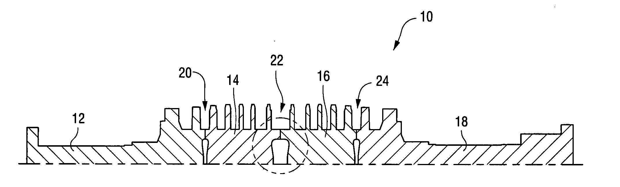
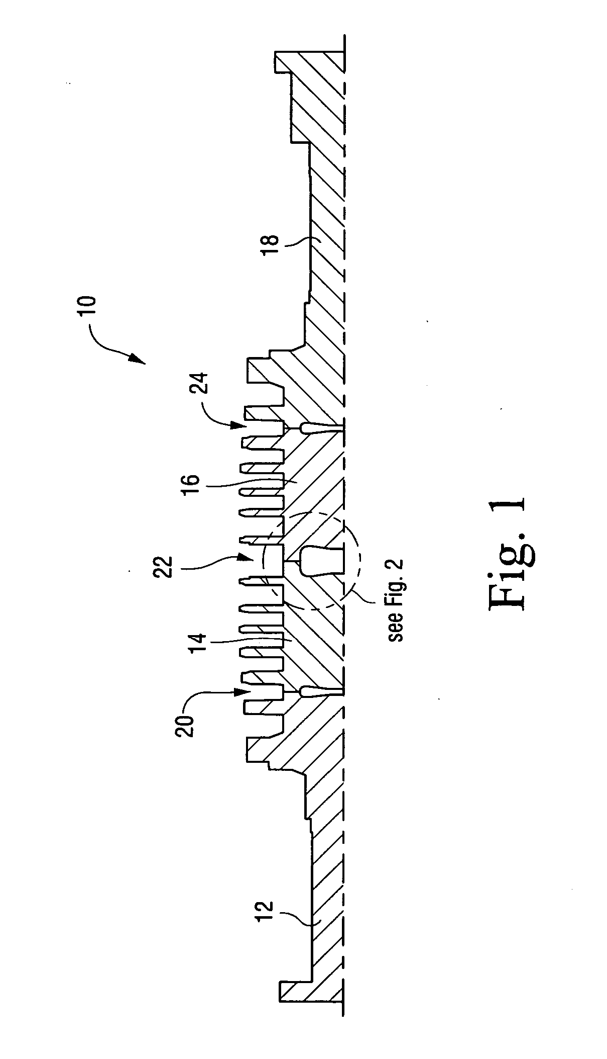
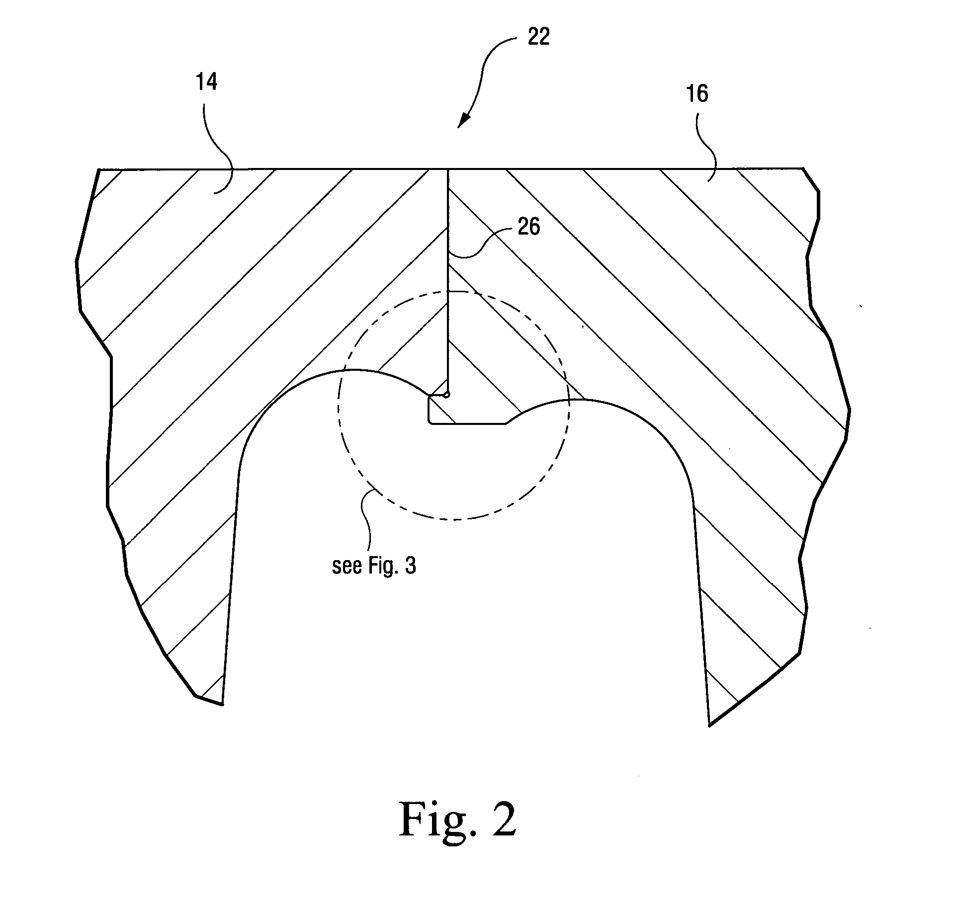
[0013] Referring to FIGS. 1 and 2, a rotor 10 for a turbine (e.g., a steam turbine) is constructed as a welded assembly of four rotor forging components (or simply, forgings) 12, 14, 16 and 18 joined at three weld joints 20, 22 and 24. The weld joints in the exemplary embodiment are substantially identical, and only one need be described in detail here. Weld joint 22 between components 14 and 16 is best seen in the enlarged detail of FIG. 2. The rotor forging component 14 is machined in a weld prep process to include a first radial weld surface 26 perpendicular to the longitudinal axis of the rotor, and a first annular rabbet surface 28 (FIG. 3) that extends axially, parallel to the longitudinal axis.

[0014] The rotor forging component 16 is machined to include a second radial weld surface 30 adapted to engage first weld surface 24, and an annular axial lip 32 radially inward of the first rabbet surface 28. The lip 32 is formed to include a second annular, axially extending rabbet s...


PUM

PropertyMeasurementUnit
radial lengthaaaaaaaaaa
areaaaaaaaaaaa
stressaaaaaaaaaa

Abstract

A weld prep joint for welding a pair of axially aligned first and second machine rotor forgings includes a first weld joint configuration in an end of the first rotor forging including a first radial weld surface and a first axial rabbet surface; a second weld joint configuration on an end of the second rotor forging including a second radial weld surface adapted to engage the first radial weld surface, a second axial rabbet surface adapted to engage the first axial rabbet surface, and a third radial non-weld surface extending radially inwardly of the second rabbet surface and axially offset from the second radial weld surface.

Description

BACKGROUND OF THE INVENTION [0001] This invention relates to electron beam or laser welding and, specifically, to a steam turbine rotor weld prep joint configured to facilitate a single pass full penetration fusion weld of axially-aligned rotor forgings using a focused high energy beam. [0002] Certain turbine rotors are comprised of a one piece “monoblock” forging. More recently, to facilitate manufacture, shipment and assembly, discrete rotor components or forgings have been welded together to duplicate the original single forging. Welded rotors have not been completely satisfactory, however, due to difficulty in alignment and preparation of end faces for welding. BRIEF DESCRIPTION OF THE INVENTION [0003] This invention provides a unique weld prep joint for rotor forgings having two geometry aspects that are particularly beneficial. First, the weld prep joint is configured to provide a rabbet interference fit for consistent concentric assembly of axially-aligned rotor forging compo...

Claims


Application Information

Patent Timeline
Patent Type & Authority Applications(United States)
IPC IPC(8): B23K26/20B23K15/00
CPCB23K15/04B23K26/285F01D5/063B23K2201/001B23K33/006B23K26/282B23K2101/001
Inventor BURNETT, MARK EDWARDSPIEGEL, LYLE B.YEHLE, GARY EDWARDBABCOCK, WILLIAM EDWARD
Owner GENERAL ELECTRIC CO
Why Eureka
Try Eureka