Vacuum suction head

a vacuum suction head and vacuum technology, applied in the direction of gripping heads, thin material processing, article separation, etc., can solve the problems of affecting the clearance of the upper and lower glass substrate, and affecting the quality of the produ

Inactive Publication Date: 2006-10-19
MITSUBOSHI DIAMOND IND CO LTD
View PDF14 Cites 16 Cited by
  • Summary
  • Abstract
  • Description
  • Claims
  • Application Information

AI Technical Summary

Benefits of technology

[0021] Herein, the elastic member may be a skirt pad formed into a skirt shape, and include: a plate part which supports the vacuum suction pad from behind a suction surface; an annular part which is formed into a thick annular shape on an outer edge of the pla

Problems solved by technology

If the plurality of vacuum suction pads 1 are attached to the vacuum suction device with the suction surfaces thereof out of the above-mentioned attachment tolerance range, the liquid crystal panel 2 is conveyed while imperfectly sucked, whereby the liquid crystal panel 2 might drop when conveyed, or might be pressed by the vacu

Method used


Image

  • Vacuum suction head
  • Vacuum suction head
  • Vacuum suction head

Examples


embodiment 1

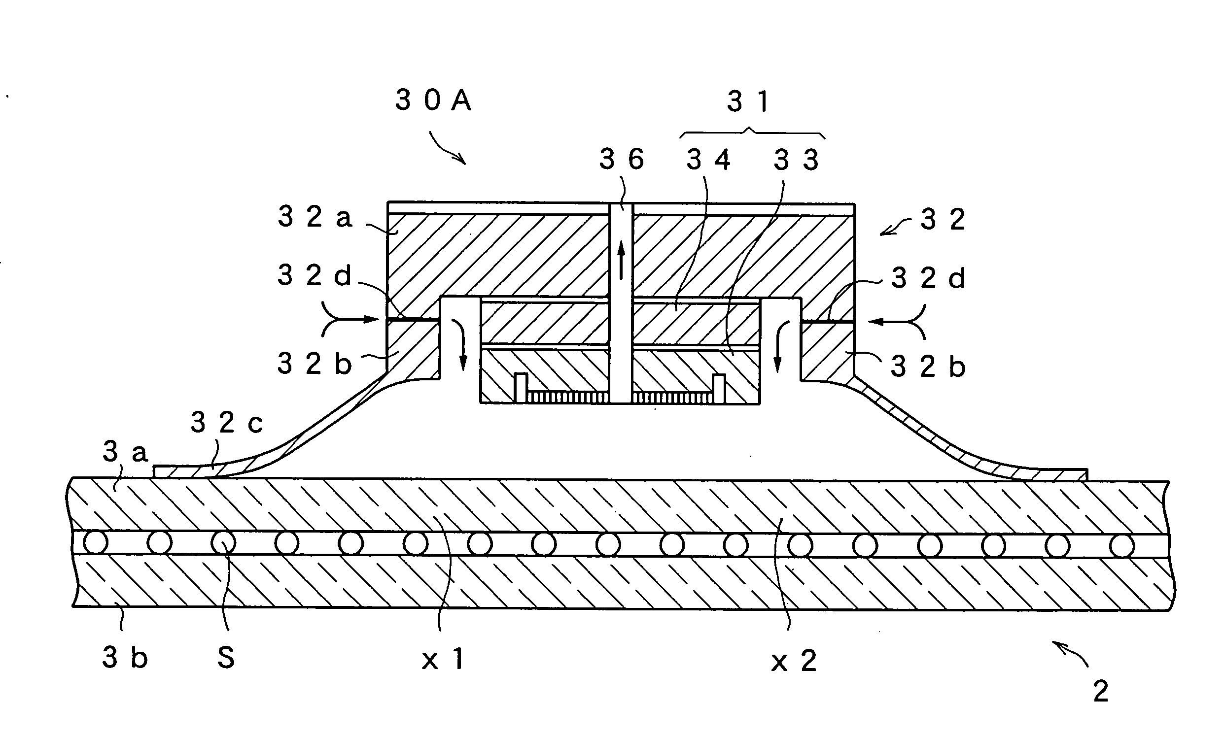
[0045] A vacuum suction head in Embodiment 1 of the present invention will be described with reference to the drawings. A substrate herein means a single-plate semiconductor wafer, a ceramic substrate, a glass substrate, a plastic substrate, a transmissive-type projector substrate which is a laminated substrate, PDP (plasma display) which is a flat panel display, a reflective-type liquid projector substrate, a liquid crystal panel, an organic EL element substrate and the like. While the vacuum suction head of the present invention is effectively applicable to a liquid crystal panel and a mother liquid crystal panel with no spacer inserted therein, an example of a liquid crystal panel with spacers inserted therein will be described herein. FIG. 11 is an end view showing a structure of a vacuum suction head 30A in Embodiment 1. The vacuum suction head 30A includes a vacuum suction pad 31 and a skirt pad 32. FIG. 12 is a plan view showing a structure of a suction surface (suction disk ...

embodiment 2

[0063] Next, a vacuum suction head in Embodiment 2 of the present invention will be described with reference to the drawings. FIG. 16 is an end view showing a structure of a vacuum suction head 40 in Embodiment 2. The vacuum suction head 40 includes the vacuum suction pad 31, a plate part 41 and a sponge pad 42. The vacuum suction pad 31 and the sponge pad 42 are concentrically attached to the plate part 41.

[0064] Since the structure of the vacuum suction pad 41 is the same as that shown in FIGS. 11 and 12, descriptions on the constituents thereof are omitted. The sponge pad 42 is an elastic member having the same function as the skirt pad 32 shown in FIG. 11. The sponge pad 42 is made of porous rubber and is cylindrically formed. As the porous rubber, especially one with large loss of pressure is used. Used herein is a sponge body of EPT (Ethylene Propylene Terpolymer) which is excellent in weather resistance, heat resistance and aging resistance. As the sponge body, an open-cell ...


PUM


Abstract

An etchable plate-shaped material is used as a vacuum suction pad 31. On one surface thereof, a large number of independent protruded portions and recessed portions are formed to provide a suction part 33b. Further, a periphery of the suction part is annularly formed to provide an airtight part 33a. When the vacuum suction pad 31 comes close to a substrate to be sucked, a skirt pad 32 with a slit 32d is integrally formed in the shape of a hemmed hat using an elastic member, in order to block outside air into a peripheral space of the vacuum suction pad 31. With this arrangement, it is possible to prevent the substrate from being locally deformed when the substrate is sucked by discharging air from a suction port 36 and to widen a clearance between the vacuum suction pad and the substrate such as a liquid crystal panel, at which the suction is possible.

Description

TECHNICAL FIELD [0001] The present invention relates to a vacuum suction head for holding and sucking a substrate when conveyed. The substrate herein means a single-plate semiconductor wafer, a ceramic substrate, a glass substrate, a plastic substrate, a transmissive-type projector substrate which is a laminated substrate, PDP (plasma display) which is a flat panel display, a reflective-type liquid crystal projector substrate, a liquid crystal panel, an organic EL element substrate, and the like. Herein, a glass substrate and the like having a small thickness are called brittle material substrates. In the following, description will be given using the liquid crystal panel as an example. BACKGROUND ART [0002] A conveyor robot or the like is used for supplying and removing a material to and from a substrate processing device and the like. FIG. 1 shows a vacuum suction pad 1 of a first conventional example for conveying a substrate for use in a vacuum suction device of the conveyor rob...

Claims


Application Information

Patent Timeline
IPC IPC(8): B25J15/06B65H3/08H01L21/683
CPCB25B11/005B25B11/007H01L21/6838B65G47/91B65H3/0883B25J15/0616Y10S901/40
Inventor NAGASAWA, SHIGEKITAKAMATSU, KIYOSHI
Owner MITSUBOSHI DIAMOND IND CO LTD
Why Eureka
Try Eureka