
Semiconductor integrated circuit and method for testing connection state between semiconductor integrated circuits

a technology of integrated circuits and semiconductors, applied in semiconductor/solid-state device testing/measurement, instruments, measurement devices, etc., can solve the problems of difficult to test the extent to which the semiconductor chips are connected, unreliable contact, and connection failure at bumps, etc., to prevent an increase in the number of wiring lines, accurately detect bump contact failure, and accurate detection of bump contact failure

Inactive Publication Date: 2006-10-19
SONY CORP
View PDF3 Cites 26 Cited by
  • Summary
  • Abstract
  • Description
  • Claims
  • Application Information

AI Technical Summary

Benefits of technology

[0019] Therefore, elimination of unreliable-contact devices by testing the connection state of bumps improves the package quality.
[0037] According to another embodiment of the present invention, a method for testing a connection state between an output terminal of a first semiconductor integrated circuit and an input terminal of a second semiconductor integrated circuit includes the steps of controlling the first semiconductor integrated circuit to output a voltage of a predetermined level from the output terminal; controlling a testing circuit that is provided in the second semiconductor integrated circuit and that changes a resistance value between the input terminal and a predetermined potential to change a voltage of the input terminal; comparing the voltage of the input terminal and a predetermined threshold in the second semiconductor integrated circuit; and testing the connection state according to a result of the step of comparing. It is therefore possible to accurately detect contact failure of bumps used for connection between semiconductor chips. Further, a single test terminal provided for a semiconductor chip is sufficient for testing, thus preventing an increase in the number of wiring lines from the semiconductor chip.

Problems solved by technology

In the connection testing methods disclosed in the publications mentioned above, although it is possible to determine whether or not semiconductor chips are connected, it is difficult to test the extent to which the semiconductor chips are connected.
In the manufacturing process, the bumps can be connected with a deviation from the normal positions, leading to unreliable contact to some extent.
If such unreliable-contact semiconductor devices are assembled into electronic equipment and are sold as products in the market, connection failure at the bumps can occur depending on the use environment.
Particularly, in an environment where the products are used in places with a large difference in temperature and / or humidity, connection failure is more likely to occur.

Method used


Image

  • Semiconductor integrated circuit and method for testing connection state between semiconductor integrated circuits
  • Semiconductor integrated circuit and method for testing connection state between semiconductor integrated circuits
  • Semiconductor integrated circuit and method for testing connection state between semiconductor integrated circuits

Examples


Embodiment Construction

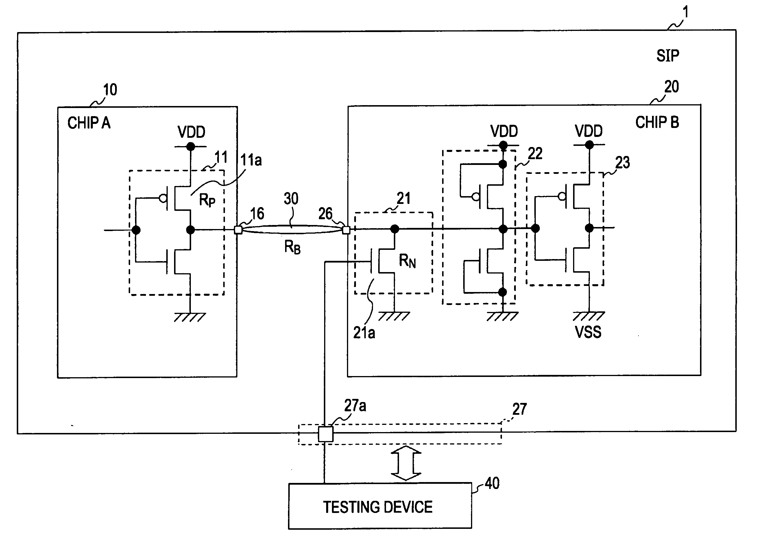
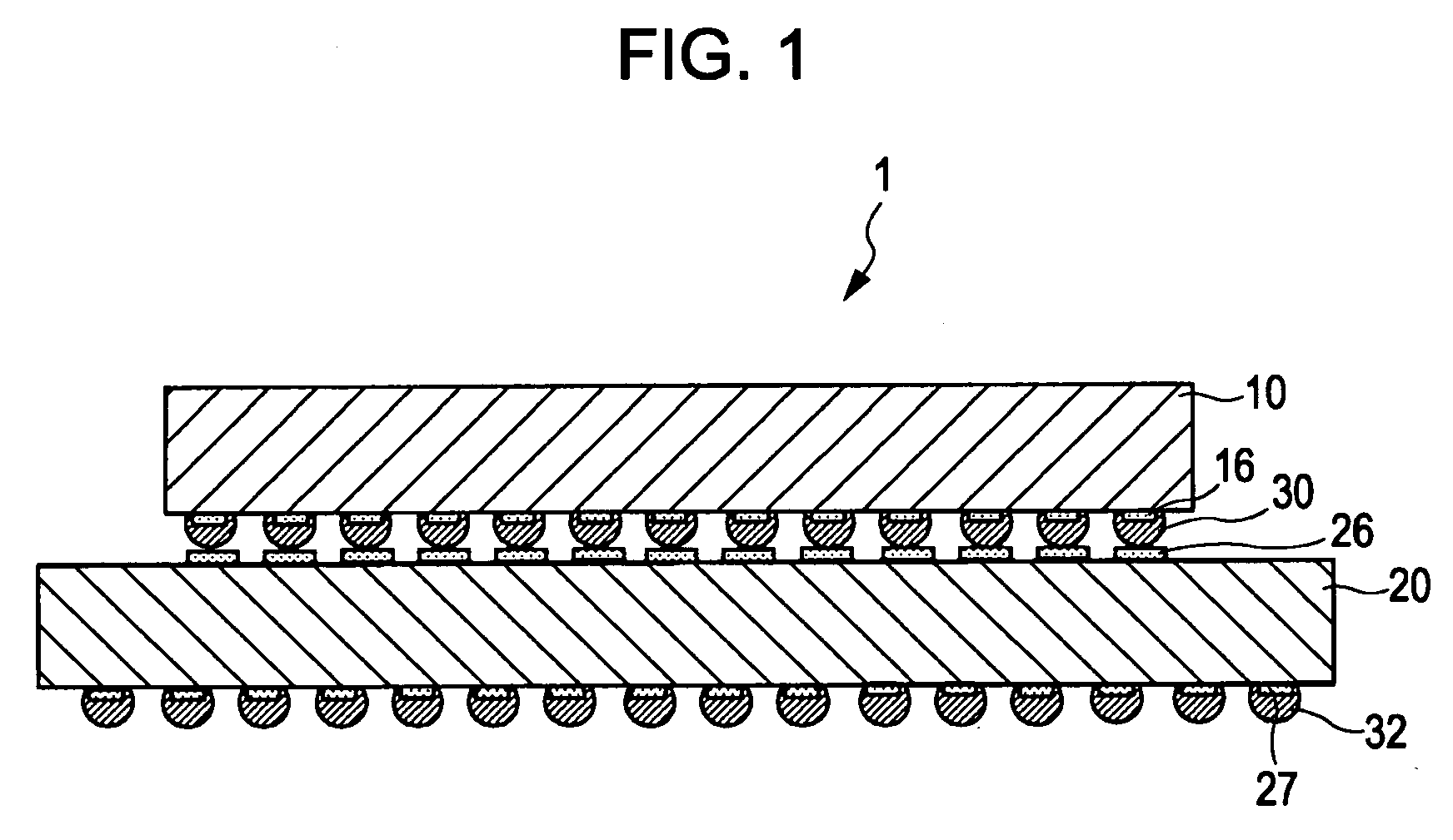
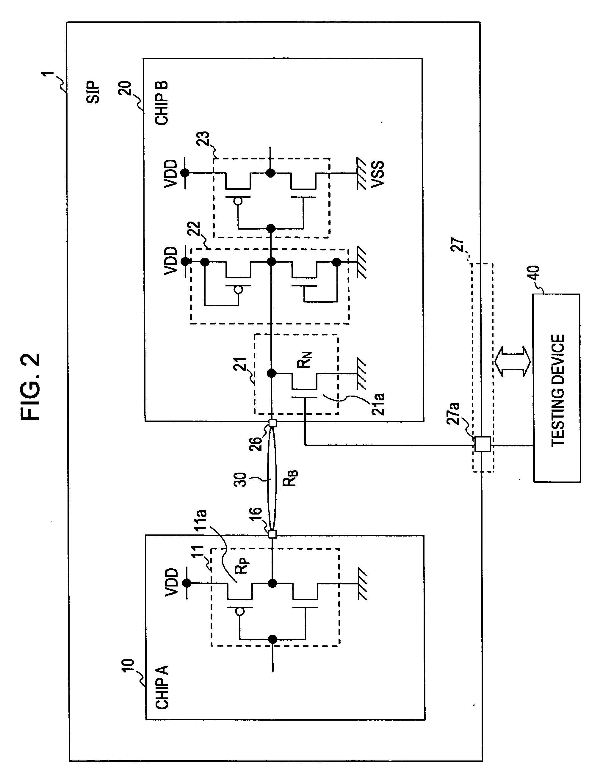
[0043] An embodiment of the present invention will be described hereinbelow. FIG. 1 is a diagram showing the external appearance of a semiconductor device according to an embodiment of the present invention. FIG. 2 is a diagram showing the principle for testing a bump-connection state in the semiconductor device according to an embodiment of the present invention. FIG. 3 is a diagram showing an operation of testing a bump-connection state in a semiconductor device according to an embodiment of the present invention.

[0044] As shown in FIG. 1, a semiconductor device 1 according to an embodiment of the present invention includes a first semiconductor chip 10 (a first semiconductor integrated circuit according to an embodiment of the present invention), and a second semiconductor chip 20 (a semiconductor integrated circuit or a second semiconductor integrated circuit according to an embodiment of the present invention). The semiconductor device 1 has a chip-on-chip SiP structure in whi...


PUM


Abstract

A semiconductor integrated circuit including an input terminal and an input circuit connected to the input terminal includes the following elements. A testing circuit is provided between the input terminal and the input circuit, and changes a resistance value between the input terminal and a predetermined potential. A test terminal is adapted to operate the testing circuit.

Description

CROSS REFERENCES TO RELATED APPLICATIONS [0001] The present invention contains subject matter related to Japanese Patent Application JP 2005-116209 filed in the Japanese Patent Office on Apr. 13, 2005, the entire contents of which are incorporated herein by reference. BACKGROUND OF THE INVENTION [0002] 1. Field of the Invention [0003] The present invention relates to semiconductor integrated circuits. More specifically, the present invention relates to a semiconductor integrated circuit using bump technology and a method for testing a connection state between semiconductor integrated circuits. [0004] 2. Description of the Related Art [0005] With the recent demands for high-performance high-speed electronic devices, such as personal computers (PCs), home game devices, and portable terminals, demands for higher density and more layers in semiconductor integrated circuits used for the electronic devices have increased. [0006] One of the mainstream methods for increasing the density of ...

Claims


Application Information

Patent Timeline
Patent Type & Authority Applications(United States)
IPC IPC(8): G01R31/26
CPCG01R31/046G01R31/31717G01R31/2812G01R31/70H01L22/00
Inventor SHIMIZUME, KAZUTOSHIMIZOGUTI, HIROAKI
Owner SONY CORP
Learn More